GDO-10v1 ToroTM Roll Up Garage Door Opener Featuring TrioCode™ Technology Part number # 13244 (Manual) INSTALLATION INSTRUCTIONS | OWNERS COPY
WARNING: It is vital for the safety of persons to follow all instructions. Failure to comply with the installation instructions and the safety warnings may result in serious personal injury and/or property and remote control opener damage. Please save these instructions for future reference.
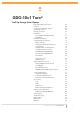
GDO-10v1 Toro® Roll Up Garage Door Opener Important Safety Instructions Features Controllers Input And Output Operating Controls Package Contents Installation Pre-installation Requirements Installation PE Beams Installation Programming The Opener Menu Structure Viewing And Editing Parameters Setting Limits Setting Limits: Via Transmitter Setting Pedestrian Position Standard Operating Modes 04 06 08 09 10 11 11 12 14 15 15 16 17 18 27 28 Control Board Adjustments 30 Time Clock 33 Diagnostic Tools Memor
Important Safety Instructions WARNING: It is vital for the safety of persons to follow all instructions. Failure to comply with the following Safety Rules may result in serious personal injury and/or property damage. CAUTION: If your garage has no pedestrian entrance door, an emergency access device should be installed. This accessory allows manual operation of the garage door from outside in case of power failure.
Important Safety Instructions The garage door must be well balanced. Sticking or binding doors must be repaired by a qualified garage door installer prior to installation of the opener. Frequently examine the installation, in particular cables, springs and mountings for signs of wear, damage or imbalance. DO NOT use if repair or adjustment is needed since a fault in the installation or an incorrectly balanced door may cause injury.
Features Thank you for purchasing the Automatic Technology Toro® Automatic Garage Door Opener. Designed by our renowned engineers to suit roll up doors, the Toro® will provide years of smart, simple & secure convenience to your home. Operation To open or close the door simply press open or close button on a wall control unit, button on a coded TrioCode™ hand held transmitter, optional wall mounted transmitter, or optional wall switch for two seconds.
SmartSolar™ Compatibility (optional) The opener can be fitted with a SmartSolar™ kit (Part Number 00142) for operation, where mains power access is not available. NOTE: If the door is the only entrance to the garage, a keyed cable release should be fitted external to the garage. Vacation Mode A hand held transmitter can be programmed to lock and unlock all other transmitters that have been programmed into the openers’ memory. The vacation mode can be used when the door is left idle for long periods of time.
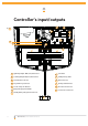
Controller’s input/outputs 12 13 fig 01 11 01 02 04 10 03 09 08 07 05 01 Light Relay Output N/O, Com, N/C Contact 08 Solar Shunt 02 Lock Relay Output N/O, Com, N/C Contact 09 Standby Battery Shunt 03 Serial Interface Connector 10 Motor Connector 04 Programmer Pg3 Connector 11 10 Amps Slow Blow Fuse 05 12 volts 6 Amp - Hr Batteries 12 24 Volts Ac In Connector 06 Engage/disengagement Handle 13 Position Sensor Connector 07 Standby Battery Charger/Solar Connector 06 8 GDO-10V1 Toro
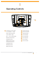
Operating Controls 17 16 15 14 14 19 18 20 fig 02 21 22 Terminal Block ( From Left To Right ) 15 Programmer PG-3 Input V+ ( P.E ) PE Beams “ + “ Supply 16 Console Previous Button IN (P.E ) PE Beams Trigger Input 17 Liquid Crystal Display V- (P.
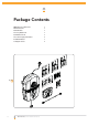
Package Contents GDO-10v1 Toro™ Drive Unit 1 Wall Control Unit 1 Network Cable 1 Accessory Guide Pack 1 Fork Extension Pack 3 Triocode™ Keyring Transmitters 2 Installation Manual 1 Locking Bar Covers 2 fig 03 10 GDO-10V1 Toro® Owner Installation Instructions
Pre-Installation Requirements IMPORTANT SAFETY INSTRUCTIONS FOR INSTALLATION Warning: Incorrect installation can lead to severe injury. Follow ALL installation instructions. NOTE: 185 Planetary chain equipment must be removed from the door prior to installation of GDO-10. 140 Door Operation The door must be in good operating condition. The maximum effort to move the door up or down, from stationary, should not exceed 150 Newtons (15 kg force) at the bottom rail. Lift the door to about halfway.
Installation Side Room For Left Hand Side Installation The minimum side room required from the edge of the door curtain is 127 mm to the inside of the door bracket when opener mounted on the door bracket (Fig. 05). Step 2 - Fitting The Opener a. b. Step 1 - Preparation a. b. Check the door’s operation: i. The door must travel smoothly and be easy to operate by hand. ii. Adjust any tight or twisted guides/ tracks iii. Clean the guides if there is any oil or wax present using a suitable white spirit.
Installation Step 3 - Mounting The Opener If the internal gear does not rotate freely switch the opener to manual by pulling the disengagement handle down (there will be a click), so that the ring gear can be rotated by hand. Slide the opener over the door axle and into the drum of the door (Fig. 07). Ensure the internal gear is pushed in as far as possible (without interfering with the door curtain) and that all of the door drum’s wheel spokes are completely between the opener’s drive forks.
PE Beams (Optional) R1=5.6K OHM GREEN,BLUE,RED,GOLD .25WATT 5% TOLERENCE RESISTANCE R1 BLACK BLACK BLACK YELLOW fig 09 RED RED RED YELLOW BLACK P.E BEAM V+ IN V− V+ IN V− Step 5 - Fitting Photo Electric (PE) Beams Locate the Photo Electric (PE) Beams in a strategic location in the doorway. Automatic Technology recommend that the sensor is placed 150 mm above the floor level and as close as possible to the door opening. Connect as per the wiring diagram (Fig. 09).
Ped’n position set up procedure. See page 27 Reprofile the door travel see page 20 Menu 10.2 CLR Tx’ers? Travel limit set up procedure. See page 17 Menu 10.1 CLR control? Menu 9.2 Test tx’ers Transmitter testing See page 35 Menu 5 Light times Parameter list 1. On after cycle time 2. On before opn time 3. On before cls time See page 38 Control input status display. See page 35 Menu 4 Lock times Parameter list 1. Open lock time 2. Close lock time 3. Pre-opn lock time 4. Pre-cls lock time.
Viewing and editing parameter View Mode (No cursor) Parameter number in sub menu Parameter name 2: Close Lock Time (sec) 0.5 fig 10 Locating parameters Parameter value Displays next parameter in list Displays previous parameter in list Enter Edit Mode Edit Mode (Cursor shown) Cursor shown 2: Close Lock Time (sec) 0.∆ Decrease value 1. 2. 3. 4. Press NEXT/PREV to navigate to the required menu. Press SET to show sub-menu. Press NEXT/PREV to go to required sub-menu.
Setting Limits Menu 11 Step 6.1 - Setting Travel Limits WARNING! Use caution when operating the manual release with the door open since it may fall rapidly due to weak or broken springs, or an improperly balanced door. CAUTION! Do not disengage the opener to manual operation with children, persons or any objects including motor vehicles within the doorway. a. b. c. d. f. g. i.
Setting Limits: Via Transmitter The GDO-10v1 has the alternate ability to set travel limits using the transmitter, allowing free movement around the garage to better assess the desired limit positions. In order to use a transmitter it must first have at least one of its buttons coded to the door controller. The function assigned to the transmitter’s buttons is of no concern here as the buttons are temporally assigned to OPEN, CLOSE and SET (Fig. 16). MENU 1 Code Transmitter fig 15 PR E S S Step 7.
Safety Obstruction Force Test WARNING! Take care when testing or adjusting the Safety Obstruction Force. Excessive force may cause SERIOUS PERSONAL INJURY and/or PROPERTY DAMAGE. Step 8.1 - Testing Close Cycle a. b. c. Press the OPEN button to open the door. Place a piece of timber approximately 40 mm high on the floor directly under the door (Fig. 17). Press the CLOSE button to close door. The door should strike the object and start to re-open. fig 17 Step 8.2 - Testing Open Cycle a. b. c.
Adjusting Safety Obstruction Forces Adjusting Safety Obstruction Force The Safety Obstruction Force is calculated automatically during setup. Adjusting this is normally only necessitated by environmental conditions such as windy or dusty areas, and areas with extreme temperature changes. Menu 2 Current Trips WARNING: Doors requiring over 400N of force to move must have PE Beams fitted for safety. fig 18 Step 9.1 Force Pressure For Close Cycle. PRESS Navigating To “Current Trips” 1. 2. 3. 4. 5. 6.
Coding transmitter menu 1 The GDO-10 can store up to five hundred and eleven (511) transmitters in its memory. Each transmitter can be allocated an alpha-numeric ID label up to eleven (11) characters in length and each button can be assigned to one of several control functions. The settings for a transmitter are represented in (Fig. 21). It shows the transmitter’s store number, ID label or serial number and the functions assigned to each of its four buttons.
Transmitter Editing Editing Transmitter Settings MENU 1 Code Transmitter Display Transmitter Record Using one of the methods below, display the required transmitters details. fig 27 PR E S S Navigating To “Edit Transmitter” Menu 1. Press NEXT to navigate to the Menu 1 (Fig. 27) . 2. Press SET to enter the transmitter edit procedure. 3. Press NEXT to enter transmitter list and edit mode. 14 ID A B SMITH OSC PED D LGT VAC fig 28 Editing Button Function Field 1.
Transmitter editing (cont.) Editing The Store Location This feature is only available when coding the first button of a new transmitter. 1. Press NEXT or PREV to move cursor over Store No. (Fig. 30) 2. Press UP or DOWN to select new Store No. 3. Press SET to Confirm or NEXT/PREV to move to next field. This is useful when managing transmitters using a scheme which ties the store location to the transmitter’s owner.
Transmitter management The GDO-10 provides a transmitter listing facility which enables the user to find a transmitter location within memory. Once located a stored transmitter can be replaced, deleted, edited, copied or, if the location is empty, a new transmitter can be coded. MENU 1 Code Transmitter PRESS fig 35 PRESS Method 1 - Go To The Start Of The List Step 1. Accessing The List Menu 1. Press NEXT to navigate to the Menu 1 (Fig. 35). 2. Press SET to enter the transmitter edit procedure. 3.
Transmitter management Code Operation (location used) MENU 1.2 Delete TX# 14 If the code operation is selected for a location that already contains a transmitter, then the BASIC CODE TRANSMITTER PROCEDURE will be initiated and the new transmitter will replace the existing one. Note that the button functions and name of the existing transmitter will be transferred to the new transmitter. This procedure is of great convenience when replacing a lost transmitter.
Remote Code Set Procedure If a transmitter is already coded into the opener, additional transmitters can be coded without being in direct contact with the opener’s control panel. PRESS Existing transmitter fig 43 NOTE: Only the function of the existing transmitter button can be assigned to new transmitter. Please read instructions prior to proceeding - there is a time-out facility for security reasons. Step 11.
Setting Pedestrian Position Menu11 Pedestrian Access Position After completing the limit setup procedure the Pedestrian access position is automatically set to a position which is in the middle of the door travel. The position can be manually set by following the SETTING PEDESTRIAN POSITION procedure. MENU 11.3 Set Pedestrian fig 46 NOTE: Before setting the pedestrian access position the door must be in the fully closed position. PR E S S Step 12.1 Navigating To “Set pedestrian Menu” 1.
Standard Operating Modes Menu This section describes the standard operation of the control board with the factory set default values. Motor Control The controller drives the motor in the direction determined by the control inputs. Once a cycle is started the motor will continue to travel until: 1. The controller is instructed to stop by a control input; or; 2. The motor’s travel limit is reached; or, 3. The motor is obstructed, overloaded or stalls.
Standard Operating Modes When GPI Input Is Configured As Day Light Saving : The GPI input can be used to switch between STD time and DST (daylight savings time). The time selected is the amount of time added to STD time when DST is selected. Options are OFF, 30, 60, 90 or 120 minutes. The GPI input needs to be constantly active to show day light saving time. Open (opn) Input (Activated by OPN terminal with N/O or N/C switch, by transmitter button with OPN function assigned or by OPEN button on console).
Control Board Adjustments The opener’s standard operation can be altered by editing various parameters. This section describes the parameters and the effect they have. Use the VIEWING AND EDITING PARAMETER PROCEDURE on Page 15 to make changes. Menu 6. Motor Settings Motor speed The maximum speed the motors run at is controlled by the OPEN AND CLOSE SPEED VOLTAGE parameter. The default value is the maximum recommended for normal operation.
Control Board Adjustments cause the door to stop. The next trigger will move the door in the opposite direction to that last travelled. When GPI Input Is Configured As Ped : The activation of GPI input or by transmitter button with PED function assigned will opens the door partially to allow pedestrian access but prevent vehicle access. The position the door is driven to is automatically set to halfway during setting of the travel limits, but can be adjusted to suit.
Control Board Adjustments 32 Parameter Min Max Safety Close Mode OFF On PE Beams INPUT RESPONSE MODE Sets the P.E response mode. Options are OPEN and CLOSE cycles stop, Close cycles stop or Close cycle reverse Default Step Unit Menu No. On 7.1 OPN & CLS stop CLS to stop CLS to reverse CLS to reverse 7.2 GPI INPUT MODE configure the GPI input. Options are OSC, PED and DAY LIGHT SAVING OSC, PED, DST OSC 7.
Time Clock Menu 8 The opener provides a programmable time clock which can be used to control GDO-10 on a timed basis at various times of the week. This section details the time clock operation and configuration. MENU 8.1 Set Time/Date fig 49 Time Clock Operation The time clock consists of a 7 day clock and storage for 32 programs. The clock is powered by its own battery and therefore does not loose time when the GDO10-V1 is turned off.
Time clock menu 8 The functions available are: Settings RX = Off Under this menu three sub menus are available From the time when program with RX = OFF activate, all the transmitters will be disabled. Run Programs RX = On The programs of the timer can be interrupted by selecting RUN PROGRAM off. From the time when program with RX = ON activate, all coded transmitters will be enabled.
Diagnostic Tools Menu 9 The controller provides several diagnostic tools from within the diagnostics menu (menu 9) this section details the function of each tool and its use. MENU 9 Diagnostics fig 52 Navigating To Diagnostics Menu 1. Press PREV to navigate Menu 9 (Fig. 52). 2. Press SET to display menu of available functions. 3. Press PREV or NEXT to cycle through diagnostic tool. 4. Press SET to select. Menu 9.1 Test Inputs This tool is used to view the state of the control inputs.
Diagnostic tools menu 9 Service Counter (Cycles) 60000 fig 58 1: Open Cycles (Cycles) 500 Menu 9.5 Service Counter The opener provides a periodic service counter which can be set to expire after a number of drive cycles. When expired, the opener will beep three times at the beginning of each drive cycle and a message will be displayed on the MAIN SCREEN (Fig. 58).
Accessories Installation Step 14.1 Fitting Solenoid Or Magnetic Locks Install the lock mechanism on the door as per the manufacturers instructions. See (Fig. 61) for the wiring diagram . LIGHT Menu 4. Lock Times Lock output can be programmed for both hold and pulse mode. The operation of the lock can be programmed to activate prior to the door behave differently on open cycle to that on close cycles. NO fig 61 COM SUITABLE POWER SUPPLY NC NO COM NC LOCK 1. 2. 3. 4. 5. 6.
Accessories Installation Step 15.1 Fitting Courtesy Lights An AC or DC courtesy light can be activated via an output on the door opener control board. Connect the light as per the diagram at right. (Fig. 62) WARNING: A qualified electrician must perform the installation where 240V AC power is used. LIGHT NO fig 62 COM NC NO COM NC LOCK SUITABLE POWER SUPPLY Menu 5. Light times 1. LIGHT 2. 3. 4. 5. 6. 7. 38 Press NEXT or PREV on the wall control unit to navigate to the Menu 5 Light Times.
Auto-close mode Step 16 - Setting Up Auto-Close Mode IMPORTANT NOTICE: the Auto-Close function is not available unless PE Beams are installed. Auto-close mode is a function that automatically closes the door a preset time after the PE Beams recognise that a vehicle has left the garage. The Auto-close timer only starts after the PE Beams path is broken the Auto-close timer has been set. If the PE Beams path is not broken the door will remain open until the path is broken.
Accessories Installation Parameter Min Max Default Step Unit Menu No. STD AUTO-CLOSE TIME Sets and enables the standard auto-close time 0.0 60.0 0.0 1.0 Sec 3 P.E AUTO-CLOSE TIME Sets and enables the P.E triggered auto-close time 0.0 60.0 0.0 1.0 Sec 3 PEDESTRIAN AUTO-CLOSE TIME Sets and enables the Pedestrian auto-close time 0.0 60.0 0.0 1.0 Sec 3 P.E PEDESTRIAN AUTO-CLOSE TIME Sets and enables the PE Pedestrian auto-close time 0.0 60.0 0.0 1.
SmartSolar™ Installation WARNING: Do not connect the batteries until after Step 2. 30 Watt Solar Kit Part Number 00142 is Suitable For GDO10-V1 Step 18.1 - Mount The Charger Board 1. 2. 3. 4. 5. 6. 7. 8. 9. Unplug the drive unit from mains power. Disengage motor using manual release cord. Remove the bottom cover by pressing in from sides and sliding downward. Remove the two screws and slide upward the top cover to remove it. Then remove the transformer, EMC board and mains power cable.
Replacing Back Up Batteries Step 19.1 Replacing Back Up Batteries 1. 2. 3. 4. Fig 68 5. 6. 42 GDO-10V1 Toro® Owner Installation Instructions Unplug the drive unit from mains power. Disengage motor using manual release cord. Remove the bottom cover by pressing in from sides and sliding downward. Remove the two screws and slide upward the top cover to remove it. Remove the battery bracket by undoing the battery bracket screws. Remove the batteries and replace with the same Type.
Specifications Technical Specifications Power supply 230V - 240Va.c. 50Hz Standby power 2.6 Watts Geared Motor power 150 Watts Motor type 24Vd.c. Permanent Magnet Maximum door opening: Height: Width: Weight: 5500mm 5100mm 270kg Opener Limits Travel 5.
Troubleshooting Symptom Possible cause Remedy Door will not operate Mains power not switched on. Switch on mains power. Door is obstructed. Remove obstruction. Door is locked or motor jammed. Unlock door or remove jam. Door tracks/hardware damaged. Door requires service/repair by qualified technician. The stop function is activated Deactivate the stop switch/timer The opener is in “vacation mode” Turn off “vacation mode”.
Maintenance Maintenance Yearly Whilst your opener does not require any periodic maintenance, the door that it is fitted to does. Your garage door is a large, heavy, moving object and should be tested regularly to ensure it is in good condition. A poorly maintained door could cause fatal or serious injuries or serious damage to property. Automatic Technology suggests you contact your installer to perform an annual door service.
Spare Parts fig 69 46 GDO-10V1 Toro® Owner Installation Instructions
Warranty And Exclusion Of Liability 1. This warranty is an addition to any non-excludable conditions or warranties that are implied into this contract by relevant statute, including the Trade Practices Act 1974 (Cwth). 2.
© May 2008 Automatic Technology (Australia) Pty Ltd. All rights reserved. TrioCode™ , Toro TM and SmartSolar TM are trademarks of Automatic Technology (Australia) Pty Ltd. No part of this document may be reproduced without prior permission. In an ongoing commitment to product quality we reserve the right to change specification without notice. E&OE.