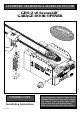
AUTOMATIC TECHNOLOGY AUSTRALIA PTY LTD GDO-2 v6 SecuraLift® GARAGE DOOR OPENER SecFeatur ing u Cod r a C Tece Hop od hno pin e® log g y y OWNERS COPY Installation Instructions P/N: 13226 Warning: It is vital for the safety of persons to follow all instructions. Failure to comply with the installation instructions and the safety warnings may result in serious personal injury and/or property and remote control opener damage. Please save these instructions for future reference.
IMPORTANT SAFETY INSTRUCTIONS Warning - It is vital for the safety of persons to follow all instructions. Failure to comply with the following Safety Rules may result in serious personal injury and/or property damage. For ADDITIONAL SAFETY protection we STRONGLY recommend the fitting of a Photo Electric Beam. In most countries Photo Electric Beams are mandatory on all garage doors fitted with automatic openers.
PRODUCT FEATURES Thank you for purchasing the SecuraLift® Overhead Garage Door Opener. The opener is designed to suit residential sectional and one piece tilt up doors. The components and materials used in this automatic opener are of the latest technology and highest quality. Listed below are some of the many features. OPERATION To open or close the door simply press the hand held transmitter, the wall mounted transmitter, or optional wall switch for two seconds.
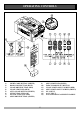
OPERATING CONTROLS 1. LIGHT CODE button (White) is used for storing or erasing the transmitter button (code) you wish to use to turn the opener’s courtesy light on and off. 6. RESET button is used to initialise and set the door/opener operating parameters, including cycle times and obstruction force settings. 2. DOOR CODE button (Blue) is used for storing or erasing the transmitter button (code) you wish to use to command the door to open, stop or close. 7.
OPERATING CONTROLS 1) 2) 3) 4) 5) 6) 7) 8) LIGHT CODE BUTTON (WHITE) DOOR CODE BUTTON (BLUE) CLOSE DRIVE BUTTON (RED) CLOSE LIMIT LED (RED) AUTO CLOSE BUTTON (WHITE) SET BUTTON (YELLOW) O/S/C BUTTON (YELLOW) OPEN DRIVE BUTTON (GREEN) 9) 10) 11) 12) 13) 14) 15) 5 OPEN LIMIT LED(GREEN) FORCE MARGIN SET BUTTON CLOSE LIMIT ADJUST SCREW (RED) OPEN LIMIT ADJUST SCREW (GREEN) P.E.
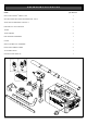
PACKAGE CONTENTS ITEM QUANTITY GDO-2 SECURALIFT® DRIVE UNIT 1 SECURACODE® KEY RING TRANSMITTER - PTX-4 2 WALL MOUNT BRACKET FOR PTX-4 1 BATTERY A23 12V ALKALINE 2 TUBES 5 TUBE INSERTS 4 PIPE SUPPORT ASSEMBLY 1 CHAIN 1 SHUTTLE/TROLLEY ASSEMBLY 1 DOOR ATTACHMENT ARMS 2 ACCESSORY PACK 1 INSTALLATION MANUAL 1 6
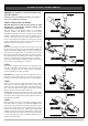
TUBE/PIPE ASSEMBLY IMPORTANT SAFETY INSTRUCTIONS FOR INSTALLATION FIG. 1 Warning: Incorrect installation can lead to severe injury. Follow ALL installation instructions. CHECK OPERATION OF DOOR BEFORE BEGINNING THE INSTALLATION OF THE SECURALIFT® AUTOMATIC OPENER CHECK THE OPERATION OF THE DOOR. The door must be well balanced and be in a reasonable operating condition. You should be able to lift the door smoothly and with little resistance. It should stay open around 900mm to 1200mm above the floor.
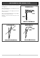
DETERMINE THE DOOR TYPE Determine which type of garage door you have as illustrated below. (Fig. 5 - 7). FIG. 5 z For a sectional (panel) door on tracks (Fig. 5) proceed with the installation from Step 5. z For a one piece door on tracks (Fig. 6) proceed with the installation from Step 5. z For a one piece door without tracks (on springs) (Fig. 7) proceed with the installation from Step 9. Remember - a one piece door without tracks requires a 7 tooth drive sprocket. FIG. 6 FIG.
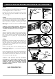
MOUNTING OPENER FOR TRACK TYPE DOOR STEP 5 FIG. 8 Open the door and find the highest point of travel of the top door panel. Using a level, transfer this height to the wall above the door (Fig. 8) and mark a line 60mm above it. Determine the centre point on the wall above and on top of the door. Then draw two (2) lines 21.5mm on each side of the centre point. (Fig. 9). STEP 6 The wall bracket should be mounted 60mm above highest point of the doors travel, 21.5mm from the centre point. (Fig. 9).
MOUNTING OPENER FOR SPRING LOADED DOOR STEP 9 FIG. 12 Determine the centre of the door and mark this location on the wall above and on top of the door. Then draw two (2) lines 21.5mm on each side of the centre point. (Fig. 12). WARNING: MAKE SURE CONCRETE, BRICK WALL OR TIMBER LINTELS ARE SOLID AND SOUND SO AS TO FORM A SECURE MOUNTING PLATFORM. STEP 10 Raise the door to open position.
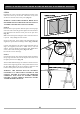
MOUNTING DOOR BRACKET AND ARMS STEP 12 FIG. 15 With the centre point of the door located, mark a line through the centre of the wall bracket onto the header wall (above the door). Using the bracket as a template mark a minimum of two holes and drill with appropriate size bit. If necessary the wall bracket can be anchored using more than two holes for a more secure fitting. If the wall bracket is mounted onto concrete or brick wall, use M8 or 5/6 loxins or dynabolts.
SETTING LIMITS STEP 15 SETTING TRAVEL LIMIT POSITIONS FIG. 18 IMPORTANT NOTE: The O/S/C button will not function until the open and close limit positions are set. 15.1 SETTING LIMIT POSITIONS 1. Plug the drive unit power cord into mains power point and switch power on. 2. Check that the door is in the closed position. If not move it by hand. Pull the manual release cord away from the door to engage the shuttle. 3. Engage the shuttle into chain index.
SETTING SAFETY OBSTRUCTION FORCE STEP 16 - SETTING OPEN AND CLOSE SAFETY OBSTRUCTION FORCE FIG. 20 The safety obstruction force is calculated automatically and set in the memory of the SecuraLift®. This applies to both the Open and Close Force.. WARNING: When step 16.1 is initiated the garage door will do a full open and close cycle automatically. Please keep door way clear to avoid any personal injury or damage to property. 16.1 TO INITIALISE OBSTRUCTION FORCE 1. Press and hold the close button (Fig.
CODING TRANSMITTERS STEP 17 - STORING TRANSMITTER CODES FIG. 22 PRESS AND HOLD DOOR CODE BUTTON Make sure to connect the battery to the transmitters. The memory in the openers receiver can store up to 27 different remote control transmitters. 17.1 STORING TRANSMITTER CODE 1. Press and hold the Door Code button (Fig. 22). 2. Press the button (one of four) on the transmitter you would like to use to control the door for two seconds. 3. Pause for two seconds.
CODING TRANSMITTERS STEP 19 - SETTING THE TRANSMITTER TO OPERATE THE COURTESY LIGHT FIG. 25 The transmitter can be programmed to operate the courtesy light on the door opener. 1. Press and hold Light Code button (Fig. 25). 2. Press the button on the transmitter you would like to use to switch on the light for two seconds 3. Pause for two seconds. Press the same button again on the transmitter for two seconds. 4. Release all buttons to store the transmitter in memory. 5.
P.E. BEAM AND AUTO CLOSE STEP 21 - FITTING THE SAFETY PHOTO ELECTRIC BEAM SENSOR (OPTIONAL) FIG. 28 Locate the Photo Electric Beam (P.E.) normally closed contact type in a strategic location within doorway. We recommend 150mm above the floor level and as close as possible to the door opening, inside the garage. Remove shunt from P.E connector (Fig. 28) and connect the plug from the P.E. wiring harness to P.E. connector (Fig. 29). The wiring diagram is for Model PHBE (Order Code 90214).
PARAMETERS DOOR STATUS INDICATORS DOOR OPENER STATE OPEN GREEN OPEN LED RED CLOSE LED YELLOW DOOR STATUS LED COURTESY LIGHT BEEPER ON ON CLOSE FLASHING OPENING FLASHING CLOSING DOOR TRAVEL STOPPED FLASHING DOOR OBSTRUCTED WHEN OPENING FLASHING FLASHING BEEPS ON & OFF DOOR OBSTRUCTED WHEN CLOSING DOOR OVERLOADED FLASHING BEEPS ON & OFF FLASHES TEN TIMES ALTERNATING ALTERNATING FLASHES FLASHES DOOR & OPENER APPROACHING OVERLOAD BEEPS WHILE DOOR IS MOVING DOOR APPROACHED OVERLOAD 3 TIMES I
TROUBLE SHOOTING SYMPTOM POSSIBLE CAUSE REMEDY Door will not operate. Mains power not switched on. Door is obstructed. Door is locked or motor jammed. Door tracks/hardware damaged. Switch on mains power. Remove obstruction. Unlock door or remove jam. Door requires service/repair by qualified technician. Door starts to close but automatically reverses to open position. Adverse weather conditions (wind or cold) causing door to stiffen and become tight in the tracks. Possible obstruction in the doorway.
SPARE PARTS LIST WHEN ORDERING SPARE PARTS PLEASE QUOTE THE ORDER CODE NUMBER TO YOUR YOUR INSTALLER/DISTRIBUTOR 19
WARRANTY AND EXCLUSION OF LIABILITY 1. This warranty is an addition to any non-excludable conditions or warranties that are implied into this contract by relevant statute, including the Trade Practices Act 1974 (Cth). 2.