GDO-9v2 SecuraLift® Overhead Garage Door Opener Featuring TrioCode™ Technology Part # 13212 (Manual) INSTALLATION INSTRUCTIONS | OWNERS COPY
WARNING: It is vital for the safety of persons to follow all instructions. Failure to comply with the installation instructions and the safety warnings may result in serious personal injury and/or property damage. Please save these instructions for future reference.
GDO-9v2 SecuraLift® Overhead Garage Door Opener Important Safety Instructions 4 Features 6 Operating Controls 8 Kit Contents 10 Installation 11 Knockdown C-Rail Assembly 11 C-Rail Attachment 12 Determine Door Type 13 Mounting - Track Type Door 14 Photo Electric Beam Installation 23 Mounting - Spring Loaded Door 15 Auto-Close Setup 23 Mounting Door Bracket & Arms 16 SmartSolar™ Installation 24 17 Battery Back Up installation 25 Programming the Opener Setting Travel Limits - C
Important Safety Instructions WARNING: It is vital for the safety of persons to follow all instructions. Failure to comply with the following Safety Rules may result in serious personal injury and/or property damage. CAUTION: If your garage has no pedestrian entrance door, an emergency access device should be installed. This accessory allows manual operation of the garage door from outside in case of power failure. For ADDITIONAL SAFETY protection we STRONGLY recommend the fitting of a Photo Electric (P.E.
Important Safety Instructions The unit should be installed so that it is protected from the elements. It should not be exposed to water or rain. It is not to be immersed in water or sprayed directly by a hose or other device. The garage door must be well balanced. Sticking or binding doors must be repaired by a qualified garage door installer prior to installation of the opener. Frequently examine the installation, in particular cables, springs and mountings for signs of wear, damage or imbalance.
Features Thank you for purchasing the Automatic Technology GDO-9v2 SecuraLift® Overhead Garage Door Opener. Designed to suit sectional overhead and one piece tilt up doors, the components and materials used ensure this opener will provide years of smart, simple and secure operation. Listed below are some of the many features: Operation To open or close the door simply press a button on a TrioCode™ handheld transmitter, a wall mounted transmitter, or optional wall switch for two seconds.
SmartSolar™ and Battery Back Up Compatibility (optional) The opener can be fitted with a SmartSolar™ or Battery Back Up kit for operation in the event of a power outage, or where mains power access is not available. NOTE: If the door is the only entrance to the garage, and a battery back up kit is not fitted, a keyed cable release should be fitted external to the garage.
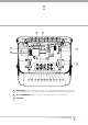
Operating controls 01 02 03 04 P.E. Shunt. The shunt has to be removed when connecting a Photo Electric Beam. NOTE: P.E. Shunt must only be removed when P.E. Beams are being connected, otherwise the opener will malfunction. Terminal Block. • 24V PWR is used to power devices such as: » PE (Input) for photo electric beam for safety and auto-close function. » LGT (Input) allow hard wired external trigger for the opener’s courtesy light.
18 17 01 16 02 15 03 04 05 06 07 08 09 10 11 12 13 14 16 PROG INPUT is used to connect the Automatic Technology Handheld Programmer for editing control 17 SBY-3 CONNECTOR is used to connect both Battery Back Up Kits and SmartSolar™ kits. 18 10A FUSE and receiver functions, accessing diagnostic tools, and activating special features and operating modes.
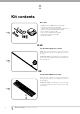
Kit contents Drive Unit 1 x GDO-9v2 SecuraLift® Trio drive unit (Fig. 01) 1 x TrioCode™ Transmitter pack (Fig. 01) (Pack includes two keyring transmitters and batteries) 1 x Wall mount transmitter with battery (Fig. 01) 2 x Door attachment arms (Fig. 01) 1 x Accessory and hardware pack (Fig. 01) 1 x Manual Disengage Cord (Fig. 01) 1 x Installation Manual fig 01 PLUS Pre-Assembled Single Piece C-Rail NOTE: The chain or belt in the one piece rail has been tensioned by the factory.
Knockdown C-Rail Assembly Start 1 Swing 2 Swing and straighten 3 Slide sleeve 4 Cut cable tie 5 Swing fig 04 7 Slide sleeve Swing and straighten 6 Turn tracks around 9 10 Screws Tension 1/2” hex bolt 8 Screws Adjust chain tension: Move the shuttle to middle of track. Use a spring scale to measure required force to pull the shuttle adjust 1/2” hex bolt to tension chain.
C-Rail Attachment Step 2 - Attach Manual Disengage Cord a. b. c. d. fig 05 If not already disengaged, flick the yellow clutch lever up so it sits perpendicular to the rail. Thread the loose end of the cord through the hole in the yellow clutch lever (Fig. 05). Thread the cord down to red toggle and knot through the spare hole. Test if secured properly by pulling back towards sprocket end to engage, and the towards door end to disengage. Step 3 - Secure C-Rail to Drive Unit a. b.
Determine the Door Type Step 4 - Determine Door Type Determine which type of garage door you have as illustrated below. (Fig. 08 to 10). For a sectional (panel) door on tracks (Fig. 08) proceed with the installation from Step 5. Track fig 08 Door Sectional door with track For a one-piece door on tracks (Fig. 09) proceed with the installation from Step 5. fig 09 One piece door with track For a one-piece door without tracks (on springs) (Fig. 10) proceed with the installation from Step 9.
Mounting on a Track Type Door WARNING: The opener must be securely fastened to structural supports, otherwise opener failure may ensue causing serious personal injury and/or property damage. Level Level Track fig 11 Track Step 5 - Determine Bracket Position Door a. Door b. c. Open the door and find the highest point of travel of the top door panel. Using a level, transfer this height to the wall above the door (Fig. 11) and mark a line 60mm above it.
Mounting on a non-Track Type Door WARNING: The opener must be securely fastened to structural supports, otherwise opener failure may ensue causing serious personal injury and/or property damage. Centre of Door Step 9 - Determine the Door’s Centre a. b. Find the centre of the door and mark this location both above the door and on top of the door. Draw two lines 21.5mm either side of this (Fig. 15). fig 15 Step 10 - Prepositioning the Opener a. b. c. Raise the door to open position.
Mounting Door Bracket & Arms Step 13 - Mounting Door Bracket The door bracket comes in two parts. The bottom plate with two mounting holes is used on its own for one piece doors. For sectional doors, the top plate is placed over the bottom plate and is fixed with four (4) screws (Fig. 19). fig 19 a. b. Mount the door bracket, or bracket assembly, on the door’s centre line one-third down the top panel (Fig. 19) using M6 or equivalent screws (not supplied), STEEL DOORS ONLY: Bracket can be welded in place.
Setting Limits Step 15.1 - Setting Travel Limits NOTE: If P.E. Beams are to be used they must be installed before setting the travel limits. WARNING! Use caution when operating the manual release with the door open since it may fall rapidly due to weak or broken springs, or an improperly balanced door. fig 23 CAUTION! Do not disengage the opener to manual operation with children, persons or any objects including motor vehicles within the doorway. a. b. c. d. e. f. g. h.
Setting Limits: via Transmitter The GDO-9v2 has the alternate ability to set travel limits using the transmitter, allowing free movement around the garage to better assess the desired limit positions. Step 16.1 - Code a Transmitter for Limit Setting a. b. c. fig 26 d. Ensure the opener is powered up. Press and hold the DOOR CODE button (Fig. 26). Press Button 1 on the transmitter for two seconds (Fig. 27). Release and pause for two seconds. Press the Button 1 again for two seconds.
Safety Obstruction Force Test WARNING! Take care when testing or adjusting the Safety Obstruction Force. Excessive force may cause SERIOUS PERSONAL INJURY and/or PROPERTY DAMAGE. Step 17.1 - Testing Close Cycle a. b. c. Press the OPERATE button to open the door (Fig. 28). Place a piece of timber approximately 40mm high on the floor directly under the door (Fig. 29). Press the OPERATE button to close door. The door should strike the object and start to re-open. fig 28 Step 17.2 - Testing Open Cycle a. b.
Adjusting Safety Obstruction Forces Adjusting Safety Obstruction Force The Safety Obstruction Force is calculated automatically during setup. Adjusting this is normally only necessitated by environmental conditions such as windy or dusty areas, and areas with extreme temperature changes. WARNING: Doors requiring over 400N of force to move must have P.E. Beams fitted for safety. fig 30 Step 18.1 - To Increase Force Pressure a. b. c. d. Hold down FORCE MARGIN SET button (Fig.
Coding Transmitters Step 19.1 - Code a Transmitter Button for Door Operation a. b. c. d. Press and hold the DOOR CODE button (Fig. 33). Press one of the four buttons on the transmitter for two (2) seconds, pause for two (2) seconds, then press the same button again for two (2) seconds. Release the DOOR CODE BUTTON. Press the transmitter button to test. fig 33 Step 19.
Remote Coding & Deleting Transmitters Step 20 - Remotely Coding Transmitters Using this method transmitters can be coded without access to the opener’s control panel as long as a precoded transmitter is available. IMPORTANT NOTE: The door or courtesy light must activate when the steps below are performed. This indicates that the pre-coded transmitter is in range of the opener, and the correct button has been pressed. fig 37 a. b. c. d. e. Take any pre-coded transmitter.
P.E. Beam & Auto-Close Step 22 - Fitting the P.E. Beams (optional) Affix the P.E. Beams in a strategic location within the doorway. We recommend 150mm above the floor level and as close as possible to the door opening, inside the garage. Remove the shunt from P.E connector (Fig. 39). Connect the wires from the P.E. wiring harness to terminal block (Fig. 40). The wiring diagram is for Model PHBE (Order Code 90214). a. b. c. Remove PE shunt fig 39 Make sure to align the beams correctly.
SmartSolar™ Installation PLEASE NOTE: Control board firmware must be v1.32 or higher for SmartSolar™ compatibility WARNING: Do not connect batteries until Step 24.3 Step 24.1 - Mount the Charger Board a. b. Fig 42 c. d. e. f. Unplug the drive unit from mains power. Remove the screws, swing open the main cover and remove the light diffuser. Then remove the transformer, EMC board (if fitted) and mains power cable. Fix the Charger Board under the timing assembly using three (3) M4x8 screws (Fig. 42).
Battery Back Up Installation Wiring diagram 4. Connect 1. Remove screws & swing cover to open Battery assembly (#01660) 5. Close cover and re-secure with screw 4 9 6 10 11 5 10 3. Mount battery and secure with item 4 & 10 8 7 1 3 2 2 3 fig 46 2. Connect wires as shown. Refer to wiring diagram. 10 Item 1. 2. 3. 4. 5. 6. 7. 8. 9. 10. Description SBY-3 Version 1.00 SBY-3 charger harness SBY-3 battery harness Pan head screw w/washer M4 x 8 Batteries cover Batteries 12V sec 12-2.
Final Set Up Step 26 - Setting of Courtesy Light Time The preset courtesy light time is three minutes. This time can be changed by the following: a. Press and hold both the AUTO CLOSE TIME and FORCE MARGIN SET buttons (Fig. 47). b. While holding in these buttons, press the OPEN button - each press will add 10 seconds to the light time. c. To decrease the time, follow Step 16(a) and press the CLOSE button - each press will deduct 10 seconds from the light time. d.
Default Settings & Specifications Factory default settings Default Step Maximum Maximum motor run time 25 Secs. - - Courtesy light time 3 Mins. 10 Secs. 4 Mins. Obstruction force margin 8 1 20 Auto close time 0 Secs 1 Sec. 4 Mins. Technical specifications Power supply 230V - 240V AC 50Hz Transformer rating 24V DC Standby power 2.2 Watts Motor power 100 Watts Motor type 24V DC permanent magnet Shuttle travel distance in the C-Rail 2.
Parameters Door Status Indicators Door Opener State OPEN LED (Green) Open On Close Opening Beeper On Flashing Closing Flashing Door travel stopped Flashing Door obstructed when opening Flashing Door obstructed when closing 28 CLOSE LED (Red) Flashing Flashing Opener overloaded Alternating flashes Door in open position with AutoClose mode selected One second flashes Pet Mode Engaged On Mains power interrupted Rapid flashes GDO-9v2 SecuraLift® Owner Installation Instructions Alternatin
Parameters Button Functions Buttons Function OPERATE Opens/Stops/Closes the door DOOR CODE Codes a transmitter button for operate function LIGHT CODE Codes a transmitter button for light function DOOR CODE & CLOSE Codes a transmitter button for pet mode LIGHT CODE & CLOSE Codes a transmitter button for vacation function FORCE MARGIN SET & OPEN Increases the obstruction force margin setting FORCE MARGIN SET & CLOSE Decreases the obstruction force margin setting FORCE MARGIN SET (then) SET Re
Troubleshooting guide Symptom Possible cause Remedy Door will not operate Mains power not switched on Switch on mains power Door is obstructed Remove obstruction Door is locked or motor jammed Unlock door or remove jam Door tracks/hardware damaged Door requires service/repair by qualified technician Adverse weather conditions (wind or cold) causing door to stiffen and become tight in the tracks Increase force margin setting.
Maintenance Maintenance Yearly Whilst your opener does not require any periodic maintenance, the door that it is fitted to does. Your garage door is a large, heavy, moving object and should be tested regularly to ensure it is in good condition. A poorly maintained door could cause fatal or serious injuries or serious damage to property. Automatic Technology suggests you contact your installer to perform an annual door service.
Parts Listing 32 GDO-9v2 SecuraLift® Owner Installation Instructions
Owner Installation Instructions GDO-9v2 SecuraLift® 33
Warranty and Exclusion of Liability 1. This warranty is an addition to any non-excludable conditions or warranties that are implied into this contract by relevant statute, including the Trade Practices Act 1974 (Cwth). 2.
Owner Installation Instructions GDO-9v2 SecuraLift® 35
© January 2008 Automatic Technology (Australia) Pty Ltd. All rights reserved. TrioCode™ and SecuraLift ® are trademarks of Automatic Technology (Australia) Pty Ltd. No part of this document may be reproduced without prior permission. In an ongoing commitment to product quality we reserve the right to change specification without notice. E&OE.