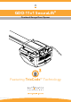
GDO-11v1 SecuraLift® Overhead Garage Door Opener Featuring TrioCode™ Technology Part # 13246 (Manual v1.
WARNING: It is vital for the safety of persons to follow all instructions. Failure to comply with the installation instructions and the safety warnings may result in serious personal injury and/or property damage. Please save these instructions for future reference.
GDO-11v1 SecuraLift® Overhead Garage Door Opener Important Safety Instructions 4 Features 6 Operating Controls 8 Kit Contents 10 Installation 11 Knockdown C-Rail Assembly 11 C-Rail Attachment 13 Determine Door Type 14 Mounting - Track Type Door 15 Photo Electric Beam Installation 25 Mounting - Spring Loaded Door 16 Key switch 25 Mounting Door Bracket & Arms 17 Auxiliary output 25 18 Battery Back Up installation 26 SmartSolar™ Installation 27 Programming the Opener Setting
Important Safety Instructions WARNING: It is vital for the safety of persons to follow all instructions. Failure to comply with the following Safety Rules may result in serious personal injury and/or property damage. CAUTION: If your garage has no pedestrian entrance door, an emergency access device should be installed. This accessory allows manual operation of the garage door from outside in case of power failure. For ADDITIONAL ENTRAPMENT protection we STRONGLY recommend the fitting of a Photo Electric (P.
Important Safety Instructions The unit should be installed so that it is protected from the elements. It should not be exposed to water or rain. It is not to be immersed in water or sprayed directly by a hose or other device. The garage door must be well balanced. Sticking or binding doors must be repaired by a qualified garage door installer prior to installation of the opener. Frequently examine the installation, in particular cables, springs and mountings for signs of wear, damage or imbalance.
Features Thank you for purchasing the Automatic Technology GDO-11v1 SecuraLift® Overhead Garage Door Opener. Designed to suit sectional overhead and one piece tilt up doors, the components and materials used ensure this opener will provide years of smart, simple and secure operation. Listed below are some of the many features: Operation To open or close the door simply press a button on a TrioCode™ handheld transmitter, or optional wall switch for two seconds.
SmartSolar™ and Battery Back Up Compatibility (optional) The opener can be fitted with a SmartSolar™ or Battery Back Up kit for operation in the event of a power outage, or where mains power access is not available. NOTE: If the door is the only entrance to the garage, and a battery back up kit is not fitted, a keyed cable release should be fitted external to the garage.
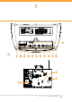
Operating controls 01 Terminal Block. » » » » » » 02 CODING LED (red) light flashes when a code is being stored or when a transmitter button is pressed. 03 DOOR CODE BUTTON is used for storing or erasing transmitter buttons for door operation 04 DOOR STATUS LED (Yellow) 05 SET button (Orange) is used during the installation phase together with the Open and MINUS (-) buttons to set the door limit positions. The Set button is also used to re-initialize the Opener.
12 fig 01 02 01 03 04 05 06 07 08 09 10 11 16 15 14 13 Owner Installation Instructions GDO-11v1 SecuraLift® 9
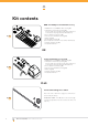
Kit contents GDO-11v1 Multipiece C Rail And Accessory 1 x GDO-11v1 SecuraLift® Ero drive unit (Fig. 02) 1 x TrioCode™ Transmitter pack (Fig. 02) (Pack includes 1x four button keyring transmitter and 1x two button keyring transmitter with batteries) 2 x Door attachment arms (Fig. 02) 1 x Accessory and hardware pack (Fig. 02) 1 x Chain (Fig. 02) 1 x C rail track pack (Fig. 02) (Pack includes three C rail sleeves and four C rail tracks) 1 x Shuttle assembly (Fig.
Knockdown C-Rail Assembly Step 1 - Knockdown C-Rail Assembly Note: If your opener came with a one piece track, proceed to Assembly step 2, page 13. a. b. c. d. e. f. Tr ac k Place track pieces on flat surface for assembly. All the track sections are interchangeable. Slide sleeve onto the track section (Fig. 05). Connect track by sliding sleeve onto next track section. Tap track assembly on piece of wood until track sections are flush. Repeat with remaining track sections.
Knockdown C-Rail Assembly Do or en d Note: Use the 12 teeth sprocket with Gdo-11v1 opener. Op en er h. en d i. fig 08 12 te et hs pr oc ke t j. k. 9 teeth sprocket fig 09 Tension hex bolt Do or en d Op en er en d fig 10 Centre of the track 12 GDO-11v1 SecuraLift® Owner Installation Instructions Engage the shuttle with the chain index and move shuttle assembly to the centre of track. Make sure the chain is engaged into the sprocket and also wrapped around the centre of the pulley.
C-Rail Attachment Step 2 - Secure C-Rail to Drive Unit a. b. Shaft Locate and insert the shaft of drive unit into the CRail’s sprocket (Fig. 11). Fix the two track brackets with four screws supplied in accessory pack (Fig. 12).
Determine the Door Type Step 3 - Determine Door Type Determine which type of garage door you have as illustrated below. (Fig. 13 to 15). For a sectional (panel) door on tracks (Fig. 13) proceed with the installation from Step 4. Track fig 13 Door Sectional door with track For a one-piece door on tracks (Fig. 14) proceed with the installation from Step 4. fig 14 One piece door with track For a one-piece door without tracks (on springs) (Fig. 15) proceed with the installation from Step 8.
Mounting on a Track Type Door WARNING: The opener must be securely fastened to structural supports, otherwise opener failure may ensue causing serious personal injury and/or property damage. Level Level Track fig 16 Step 4 - Determine Bracket Position a. b. c. Open the door and find the highest point of travel of the top door panel. Using a level, transfer this height to the wall above the door (Fig. 16) and mark a line 60mm above it. Determine the centre point on the wall above and on top of the door.
Mounting on a non-Track Type Door WARNING: The opener must be securely fastened to structural supports, otherwise opener failure may ensue causing serious personal injury and/or property damage. Centre of Door Step 8 - Determine the Door’s Centre a. fig 20 b. Find the centre of the door and mark this location both above the door and on top of the door. Draw two lines 21.5mm either side of this (Fig. 20). Step 9 - Prepositioning the Opener a. b. c. Raise the door to open position.
Mounting Door Bracket & Arms Step 12 - Mounting Door Bracket The door bracket comes in two parts. The bottom plate with two mounting holes is used on its own for one piece doors. For sectional doors, the top plate is placed over the bottom plate and is fixed with four (4) screws (Fig. 24). a. b. fig 24 Mount the door bracket, or bracket assembly, on the door’s centre line one-third down the top panel (Fig. 24) using M6 or equivalent screws (not supplied), STEEL DOORS ONLY: Bracket can be welded in place.
Setting Limits NOTE: If P.E. Beams are to be used they must be installed before setting the travel limits. Step 14.1 - Remove Controls Cover a. Swing open the controls cover to gain the access to the controls panel (Fig. 28) and swing back into its position when setup is completed. fig 28 Step 14.2 - Connect Power to the Powerhead Plug the power cord into a mains point and switch power on. The red CLOSE LIMIT LED will be flashing.
Setting Limits: via Transmitter The GDO-11v1 has the unique ability to set travel limits using the transmitter, allowing the installer to move around the garage and door to better assess the desired close and open limit positions. Step 15.1 - Power Up and Set the Datum a. Follow Steps 14.1 to 14.3 as outlined overleaf. Observe all warnings! fig 31 Step 15.2 - Code a Transmitter for Limit Setting a. b. c. Press and hold the DOOR CODE button (Fig. 31).
Safety Obstruction Force Test WARNING! Take care when testing or adjusting the Safety Obstruction Force. Excessive force may cause SERIOUS PERSONAL INJURY and/or PROPERTY DAMAGE WARNING! FOR ADDITIONAL ENTRAPMENT protection we STRONGLY recommend the fitting of a Photo Electric (P.E.) Beam. In most countries P.E. Beams are mandatory on all garage doors fitted with automatic openers.
Adjusting Safety Obstruction Forces Adjusting Safety Obstruction Force The Safety Obstruction Force is calculated automatically during setup. Adjusting this is normally only necessitated by environmental conditions such as windy or dusty areas, and areas with extreme temperature changes. WARNING: Photo electric beams must be installed if the closing force at the bottom edge of the door exceeds 400N (40kgf) fig 35 Step 17.1 - To Increase Force Pressure a. b. c. d. Hold down FORCE MARGIN SET button (Fig.
Coding Transmitters Step 18.1 - Code a Transmitter Button for Door Operation a. b. fig 38 c. d. Press and hold the DOOR CODE button (Fig. 38). Press one of the four buttons on the transmitter for two (2) seconds, pause for two (2) seconds, then press the same button again for two (2) seconds. Release the DOOR CODE BUTTON. Press the transmitter button to test. Step 18.
Coding Transmitters Step 18.4 - Code a Transmitter Button for Pet (Pedestrian) Mode a. b. c. d. e. Briefly press the DOOR CODE button three times, then press it again and hold (will beep four times on fourth press (Fig. 41)). Press one of the four buttons on the transmitter for two (2) seconds, pause for two (2) seconds, then press the same button again for two (2) seconds. Release the DOOR CODE button. Press the transmitter button to test.
Remote Coding & Deleting Transmitters Step 19 - Remotely Coding Transmitters Using this method transmitters can be coded without access to the opener’s control panel as long as a precoded transmitter is available. IMPORTANT NOTE: The door or courtesy light must activate when the steps below are performed. This indicates that the pre-coded transmitter is in range of the opener, and the correct button has been pressed. fig 43 a. b. c. d. e. Take any pre-coded transmitter.
P.E. Beams Step 20 - Fitting the P.E. Beams (optional) b. c. WARNING: When using P.E. Beams, the doorway must be clear of all obstructions and persons at all times. The location of the beams and manner in which it is installed might not give safety protection at all times. Check to make sure that the height of the beam and type used give maximum protection possible. Receiver Transmitter Model PE-2 RED RED RED RESISTOR = 2K2 0.
Battery Back Up Installation fig 49 Step 23.1 - Connect the Battery Back Up Kit a. b. c. d. e. f. g. h. Disconnect power to the opener. Swing open the light diffuser and controls cover. Remove screws marked “S” above in fig and lift up the main cover. (Fig 49). Feed the SBY-3 charger harness through the grommet on the metal plate and connect to SBY-3 as shown in wiring diagram. Mount the brackets RA (item no 9) to battery pack with item 7 and 8 Secure the battery pack to gdo-11 with 2 screws item no 5.
SmartSolar™ Installation WARNING: Do not connect batteries until Step 24.3 Step 24.1 - Mount the Charger Board a. b. c. d. e. f. g. Disconnect power to the opener. Swing open the light diffuser and controls cover. Remove screws marked “S” above in fig and lift up the main cover. (Fig 50). Remove the transformer and mains power cable. Mount the pcb support with two screws .Secure the SBY-3 charger board on to pcb support with 3 screws. (Fig. 51).
Final Set Up Step 25 - Setting the Pet Mode position The default Pet Mode height can be changed as follows: a. Make sure the door is closed, then press and hold the PLUS(+) button for six (6) seconds (Fig. 54), until you hear three beeps and the OPEN and CLOSE LEDs flash rapidly. b. Press the OPEN or CLOSE button to move the door to the desired pet mode open position. c. Press the SET button to record the new position.
Default Settings & Specifications Factory default settings Default Step Maximum Maximum motor run time 60 Secs. - - Courtesy light time 3 Mins. 10 Sec in battery back up mode Obstruction force margin 0.5 Amp 0.1 2 Amp Technical specifications Power supply 230V - 240V AC 50Hz Transformer rating 72 VA Standby power 2.2 Watts Motor power 90 Watts Motor type 24V DC permanent magnet Shuttle travel distance in the C-Rail 3.
Parameters Door Status Indicators Door Opener State OPEN LED (Green) Open On Close Opening CLOSE LED (Red) Beeper On Flashing Closing Flashing Door travel stopped Flashing Door obstructed when opening Flashing Door obstructed when closing Flashing Flashing Opener overloaded Alternating flashes Alternating flashes Pet Mode Engaged On On Mains power interrupted Rapid flashes Beeps as door moves Button Functions 30 Buttons Function OPERATE Opens/Stops/Closes the door DOOR CODE Cod
Troubleshooting guide Symptom Door will not operate Door starts to close but automatically reverses to open position Possible cause Remedy Mains power not switched on Switch on mains power Door is obstructed Remove obstruction Door is locked or motor jammed Unlock door or remove jam Door tracks/hardware damaged Door requires service/repair by qualified technician Adverse weather conditions (wind or cold) causing door to stiffen and become tight in the tracks Increase force margin setting.
Maintenance Maintenance Yearly Whilst your opener does not require any periodic maintenance, the door that it is fitted to does. Your garage door is a large, heavy, moving object and should be tested regularly to ensure it is in good condition. A poorly maintained door could cause fatal or serious injuries or serious damage to property. Automatic Technology suggests you contact your installer to perform an annual door service.
Parts Listing Owner Installation Instructions GDO-11v1 SecuraLift® 33
Warranty and Exclusion of Liability 1. This warranty is an addition to any non-excludable conditions or warranties that are implied into this contract by relevant statute, including the Trade Practices Act 1974 (Cwth). 2.
Owner Installation Instructions GDO-11v1 SecuraLift® 35
© August 2008 Automatic Technology (Australia) Pty Ltd. All rights reserved. TrioCode™ and SecuraLift ® are trademarks of Automatic Technology (Australia) Pty Ltd. No part of this document may be reproduced without prior permission. In an ongoing commitment to product quality we reserve the right to change specification without notice. E&OE.