
Installation manual
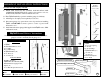

H
Drill Hole
Template
Illustration
(not to scale)
Hole
3
Hole
1
Hole
2
Gaplock
GDO Control Module
Wall/Ceiling Outlet
GDO Plug
Gaplock Wires
Cover Plate Replacement Screw
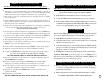
Parts List
Gaplock
Door Sensor Spring
Lock Bar
Lock Bar Hinge
Gaplock
PRO Wires
(8”)
1/4”
Bolt
(x2)
1/4”
Nut
(x2)
Drill Hole Template
Door Track
A:
B:
C:
D:
E:
F:
G:
H:
Z:
IMPORTANT INSTALLATION INSTRUCTIONS
To reduce the risk of injury or death:
READ AND FOLLOW ALL SAFETY, INSTALLATION AND
OPERATION INSTRUCTIONS. If you have any questions or do not
understand any instruction, email: tech@astlocks.com.
1.
All wiring is to be employed as required by local codes.
2.
Disconnect garage door opener from source of power before installing
Gaplock
and DO NOT reconnect opener to source of power until
instructed to do so.
3.
Install manual release signage label supplied with
Gaplock
next to GDO
wall button/console.
4.
Parts List
Parts Shown
A:
Gaplock
B: Red Manual Release lever
C: Lock Bar
D: Lock Bar Hinge
E:
Gaplock
GDO Wires
(30’)
F:
1/4”
Bolts
(x2)
G:
1/4”
Nuts
(x2)
Parts Not Shown
Drill Hole Template
Gaplock
GDO Control Module (
GCM
)
Manual Release Signage Label
Staples
(x6)
Cover Plate Replacement Screw
Tools Required For Installation
Drill
1/4”
Drill Bit
1 1/4”
Hole Saw
Small Round File
Wire Cutters
Hammer
7/16”
Wrench
Phillips Screwdriver
Gaplock
Manual Release Instructions
Locate red manual release lever atop of
Gaplock
and shift it away from the
garage door track to manually unlock garage door.
Have
Gaplock
installed by a professional in the garage door industry.
5.
4