GDO-6v3 EasyRoller® Roll Up Garage Door Opener Featuring TrioCode™ Technology Part # 13236 (Manual) v2.
WARNING: It is vital for the safety of people to follow all instructions. Failure to comply with the installation instructions and the safety warnings may result in serious personal injury and/or property and opener damage. Please save these instructions for future reference.
GDO-6v3 EasyRoller® Roll Up Garage Door Opener Important Safety Instructions Features Operating Controls Package Contents Installation Programming the Opener Safety Obstruction Force Coding Transmitters Deleting Transmitter Codes Accessories Photo Electric Beam Auto-Close Final Setup Setting of Courtesy Light Time Setting the Pet Mode Position Wall Transmitter Installation Keyswitch Connection Auxilary Output Reset all Factory Defaults SmartSolar™ Installation Battery Backup Kit Installation Parameters Doo
Important Safety Instructions WARNING: It is vital for the safety of persons to follow all instructions. Failure to comply with the following Safety Instructions may result in serious personal injury and/or property damage. CAUTION: If your garage has no pedestrian entrance door, an emergency access device should be installed. This accessory allows manual operation of the garage door from outside in case of power failure.
Important Safety Instructions The unit should be installed so that it is protected from the elements. It should not be exposed to water or rain. It is not to be immersed in water or sprayed directly by a hose or other device. The garage door must be well balanced. Sticking or binding doors must be repaired by a qualified garage door installer prior to installation of the opener. Frequently examine the installation, in particular cables, springs and mountings for signs of wear, damage or imbalance.
Features Thank you for purchasing the Automatic Technology EasyRoller® Automatic Garage Door Opener. Designed by our renowned engineers to suit Vertical Operating Continuous Curtain Roll up doors, the EasyRoller® will provide years of smart, simple & secure convenience to your home. Operation To open or close the door simply press a button on a TrioCode™ handheld transmitter, a wall mounted transmitter, or optional wall switch for two seconds.
SmartSolar™ and Battery Backup Compatibility (optional) The opener can be fitted with a SmartSolar™ or Battery Backup kit for operation in the event of a power outage, or where mains power access is not available. NOTE: If the door is the only entrance to the garage, and a battery backup kit is not fitted, a keyed cable release should be fitted externally to the garage.
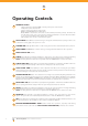
Operating Controls 01 24V (not filtered or regulated) PWR is used to power photo electric beam. PE (Input) for photo electric beam. PE (-) is used to power photo electric beam. GND is used with OSC input or AUX output O/S/C INPUT is used for the connection of a wired switch (momentary contact). This switch can then be used to open, stop or close the door. Install the wall switch in a location where the switch is out of reach of children and the garage door is visible.
17 01 PWR PE PEGND OSC AUX 16 15 11 12 13 10 09 14 02 04 03 15 16 17 06 07 08 05 JP1 SOLAR CONNECTOR the shunt must be fitted for solar operation. PROG INPUT is used to connect the Automatic Technology Handheld Programmer for editing control and receiver functions, accessing diagnostic tools, and activating special features and operating modes. SBY-3 CONNECTOR is used to connect both Battery Backup Kits and SmartSolar™ kits.
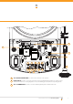
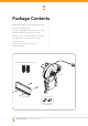
Package Contents GDO-6v3 Easyroller® drive unit w/ Easy Access Transmitter 1 TrioCode™ keyring transmitters 2 Pan head screw M4x50mm (not included in some models) 2 Nilock Hex nut M4 (not included in some models) 2 Flat washer I.D. 3/16 x 1/2 (not included in some models) 2 Spring washer I.D.
Installation Pre-Installation Requirements IMPORTANT SAFETY INSTRUCTIONS FOR INSTALLATION Warning: Incorrect installation can lead to severe injury. Follow ALL installation instructions. Door Operation The door must be in good operating condition. The maximum effort to move the door up or down, from stationary, should not exceed 150 Newtons (15kg force) at the bottom rail. The recommended force is 70N (7kg) for manual operation. Lift the door to about halfway.
Installation Step 1 - Preparation a. fig 03 b. Check the door’s operation: i. The door must travel smoothly and be easy to operate by hand. ii. Operating force on the bottom rail should be approximately 70N (7kgs) force. iii. Adjust any tight or twisted guides/tracks iv. Clean the guides if there is any oil or wax present using a suitable white spirit. The only lubricant suitable for use on door guides is silicon spray. DO NOT use WD40, RP-7, petroleum grease, or similar.
Installation Step 3 - Pin the Door Curtain Door drum Pinning the door curtain to the door drum maintains security when the opener closes and locks. a. b. c. d. Fully close the door. Mark drill holes at both ends of the drum (Fig. 07). Drill holes using 3.2mm (1/8”) drill bit. Open the door slightly for easier access, if necessary. Fit a 10 x 32mm screw and washer to each end.
Installation Step 5 - Mounting the Opener If the internal gear does not rotate freely, switch the opener to manual by pulling the disengagement handle down (there will be a click), so that the ring gear can be rotated by hand. b. Slide the opener over the door axle and into the drum of the door (Fig. 09). c. Ensure the internal gear is pushed in as far as possible (without interfering with the door curtain) and that one of the door drum’s wheel spokes is completely between the opener’s drive forks. d.
Programming the Opener Step 6.1 - Setting Travel Limits NOTE: If PE Beams are to be used they must be installed before setting the travel limits. WARNING! Use caution when operating the manual release with the door open since it may fall rapidly due to weak or broken springs, or an improperly balanced door. fig 11 CAUTION! Do not disengage the opener to manual operation with children, persons or any objects including motor vehicles within the doorway.
Programming the Opener Setting Limits: via Transmitter The GDO-6v3 has the alternate ability to set travel limits using the transmitter, allowing free movement around the garage to better assess the desired limit positions. fig 13 Step 7.1 - Code a Transmitter for Limit Setting a. b. c. d. Button 1 (Inch Open) Button 2 (Set) Step 7.2 - Setting Limits via Transmitter a. b. fig 14 Button 4 (Inch Close) Ensure the opener is powered up. Press and hold the DOOR CODE button (Fig. 13).
Safety Obstruction Force WARNING! Take care when testing or adjusting the Safety Obstruction Force. Excessive force may cause SERIOUS PERSONAL INJURY and/or PROPERTY DAMAGE. fig 15 WARNING! Photo Electric Beams must be installed where the closing force as measured on the bottom of the door is more than 400N (40kgf) Safety Obstruction Force Test Step 8.1 - Testing Close Cycle a. b. c. Press the OPERATE button to open the door (Fig. 15).
Safety Obstruction Force Adjusting Safety Obstruction Force The Safety Obstruction Force is calculated automatically during setup. Adjusting this is normally only necessitated by environmental conditions such as windy or dusty areas, and areas with extreme temperature changes. fig 17 Step 9.1 - To Increase Force Pressure Hold down the FORCE MARGIN SET button (Fig. 17). b. While holding the FORCE MARGIN SET button, press the OPEN button. Each press increases the force margin. c.
Coding Transmitters Step 10.1 - Code a Transmitter Button for Door Operation a. b. c. d. Press and hold the DOOR CODE button (Fig. 20). Press one of the four buttons on the transmitter for two (2) seconds, pause for two (2) seconds, then press the same button again for two (2) seconds. Release the DOOR CODE BUTTON. Press the transmitter button to test. fig 20 Step 10.
Coding Transmitters Step 10.5 - Code a Transmitter Button to Enable AUX OUTPUT a. fig 24 b. c. d. Briefly press the DOOR CODE button two (2) times, then press it again and hold (will beep three times on third press (Fig. 24)). Press one of the four buttons on the transmitter for two (2) seconds, pause for two (2) seconds, then press the same button again for two (2) seconds. Release the DOOR CODE button. Press the transmitter button to test. Step 11 - Easy Access Transmitter (EAT) Coding a. b. c. d.
Deleting Transmitter Codes Step 13.1 - Deleting a Stored Transmitter Code a. b. c. d. Select the transmitter you want to delete. Press and hold the DOOR CODE BUTTON (Fig. 27). Press the transmitter button you would like to delete for two (2) seconds, pause for two (2) seconds, press again for two (2) seconds and then release. Release the DOOR CODE BUTTON. The code should now be deleted. Confirm this by pressing the transmitter button - the function (e.g. door opening) should not respond. fig 27 Step 13.
Accessories Photo Electric (PE) Beams 3 4 5 fig 28 A photo electric (PE) Beams extends across the door opening. This photo electric (PE) Beams is designed to detect an obstruction while the door is closing and to send a signal to the door opener to reverse or stop the door movement. Fitting Photo Electric (PE) Beams a. 2 6 1 b. c. Attach the mounting bracket (4) to adjustment bracket (3) with the pan head screw (6) (supplied). (Fig.
Auto-Close Step 15 - Setting Up Auto-Close Mode IMPORTANT NOTICE: It is compulsory to have PE Beams installed when using Auto-Close mode. fig 31 Auto-Close mode is a function that automatically closes the door a preset time after the PE Beams recognise that a vehicle has left the garage. The Auto-Close timer only starts after the PE Beam’s path is broken. If the PE path is not broken, the door will remain open until the path is broken. If the opener incurs a physical obstruction (i.e.
Final Setup Step 16 - Setting of Courtesy Light Time The preset courtesy light time is three minutes. This time can only be changed by a “PG3” programmer. Step 17 - Setting the Pet Mode position The default Pet Mode height can be changed as follows: a. Drive and stop the door at the desired Pet Mode open position by pressing O/S/C button on the console or the transmitter button coded for O/ S/C operation. b.
Final Setup Step 20 - Auxiliary Output The auxiliary output can be used to control alarm or another garage door opener. A valid transmission from the pre-coded transmitter will cause the auxiliary output to pulse for approximately 1 (one) second. The maximum DC voltage must not exceed 35 volts DC. Maximum current must not exceed 80 ma.(Fig. 34). Step 21 - Reset all Factory Defaults a. b. c. d. Turn power to the opener off. Press and hold the SET Button (Fig 35). Turn power on while holding the SET button.
SmartSolar™ Installation WARNING: Do not connect the batteries until after Step 22.2. Step 22.1 - Mount the Charger Board 1. 2. 3. Fig 36 4. 5. 6. JP1 Solar Shunt 7. Unplug the drive unit from mains power. Disengage motor using manual release cord. Remove the main cover, timing cover and light diffuser. Then remove the transformer, EMC board and mains power cable. Fix the Charger Board under the timing cover using four (4) M4x8 screws (Fig. 36).
Battery Backup Kit Installation SBY-3 Charger board Break away slot on the timing cover and feed the battery harness through the slot Battery harness Fig 40 Cable clamp Taptite screw M4x10 SBY-3 Battery backup Control board DCB-03 Timing cover Step 23.1 - Connect the Battery Backup Kit a. b. c. d. e. f. g. h. i. j. Turn off power to the opener and disengage motor. Remove timing cover and light diffuser. Remove cable clamp and screw (Fig. 40). Retain cable clamp for later use.
Parameters Door Status Indicators Door Opener State OPEN LED (Green) Open On Close Opening Beeper On Flashing Closing Flashing Door travel stopped Flashing Door obstructed when opening Flashing Door obstructed when closing 28 CLOSE LED (Red) Flashing Flashing Opener overloaded Alternating flashes Door in open position with AutoClose mode selected One second flashes Pet Mode engaged On Mains power interrupted Rapid flashes GDO-6v3 EasyRoller® Owner Installation Instructions Alternatin
Parameters Button Functions Buttons Function OPERATE Opens/Stops/Closes the door DOOR CODE Codes a transmitter button for operate, vacation and pet functions LIGHT CODE Codes a transmitter button for light function FORCE MARGIN SET & OPEN Increases the obstruction force margin setting FORCE MARGIN SET & CLOSE Decreases the obstruction force margin setting FORCE MARGIN SET (then) SET Resets the factory default force margin settings AUTO CLOSE TIME (then) OPEN Increases the Auto-Close delay tim
Default Settings & Specifications Factory Default Settings Default Step Maximum Maximum motor run time 25 secs - - Courtesy light time 3 mins 10 secs 4 mins Obstruction force margin 13 1 20 Auto close time 0 secs 1 secs 4 mins Technical Specifications Power supply 230V - 240V A.C. 50Hz Standby power 2.2 Watts Motor power 100 Watts Motor type 24VD.C. Permanent Magnet Controller Voltage 24VD.C.
Troubleshooting Symptom Door will not operate Possible cause Remedy Mains power not switched on. Switch on mains power. Door is obstructed. Remove obstruction. Door is locked or motor jammed. Unlock door or remove jam. Door tracks/hardware damaged. Door requires service/repair by qualified technician. The opener is in “vacation mode”. Turn off “vacation mode”. Adverse weather conditions (wind or cold) causing door to stiffen and become tight in the tracks. Increase force margin setting.
Maintenance Maintenance Yearly Whilst your opener does not require any periodic maintenance, the door that it is fitted to, does. Your garage door is a large, heavy, moving object and should be tested regularly to ensure it is in good condition. A poorly maintained door could cause fatal or serious injuries or serious damage to property. Automatic Technology suggests you contact your door professional to perform an annual door service.
Spare Parts Owner Installation Instructions GDO-6v3 EasyRoller® 33
Notes 34 GDO-6v3 EasyRoller® Owner Installation Instructions
Warranty and Exclusion of Liability 1. This warranty is an addition to any non-excludable conditions or warranties that are implied into this contract by relevant statute, including the Trade Practices Act 1974 (Cwth). 2.
© July 2010 Automatic Technology (Australia) Pty Ltd. All rights reserved. TrioCode™, SmartSolar™ are trademarks and EasyRoller ® is a registered trademark of Automatic Technology (Australia) Pty Ltd. No part of this document may be reproduced without prior permission. In an ongoing commitment to product quality we reserve the right to change specification without notice. E&OE.