
Installation manual


Publication 1394-IN002B-EN-P — February 2004
2-8 1394 SERCOS Interface Connector Data
Motor Feedback Connector Pin-outs
The following table provides the signal descriptions and pin-out for
the motor and auxiliary feedback (13-pin) connectors. Motor and
Auxiliary Feedback Specifications begin on page 2-21.
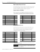
Stegmann Hiperface (SRS/SRM)
Refer to Appendix B for interconnect drawings showing how to
connect Stegmann Hiperface
®
feedback to MPL-Bxxxx-M and -S,
-Axxxx-M and -S, and 1326AB-Bxxxx-M2L and -S2L 460V motors.
Resolver Transmitter TR = 0.25
Note: TR=0.25 is an abbreviation for Transformation Ratio 0.25.
Refer to Appendix B for interconnect drawings showing how to
connect resolver transmitter feedback to MPL-Bxxxx-R and
1326AB-Bxxxx-21 Series 460V motors.
1
When using 1326AB (resolver-based) motors, the thermal switch wires pass through the TB1/TB2 noise filter
circuitry on the bottom of the axis module.
Pin Description Signal Pin Description Signal
1 Sine Differential Input+ SINE+ 8 Hiperface data channel DATA+
2 Sine Differential Input- SINE- 9 Hiperface data channel DATA-
3 Cosine Differential Input+ COS+ 10 Reserved —
4 Cosine Differential Input- COS- 11 Reserved —
5 Common ECOMM 12
Motor Thermal Switch (normally closed)
TS+
6 Encoder Power (+9V) EPWR_9VM 13
Motor Thermal Switch (normally closed)
TS-
7Reserved —
Pin Description Signal Pin Description Signal
1 Sine Differential Input+ S2 8 Reserved —
2 Sine Differential Input- S4 9 Reserved —
3 Cosine Differential Input+ S1 10 Resolver Excitation R1
4 Cosine Differential Input- S3 11 Resolver Excitation R2
5 Reserved — 12
Motor Thermal Switch (normally
closed)
1
TS+
6 Reserved — 13
Motor Thermal Switch (normally
closed)
1
TS-
7Reserved —
IMPORTANT
To meet CE requirements, combined motor power
cable length for all (up to 4) axes must not exceed
360 m (1181 ft).