
Installation manual


Publication 1394-IN002B-EN-P — February 2004
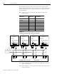
B-16 Interconnect Diagrams
The example below also shows 1394 series C axis modules with
internal brake filtering. Each axis is connected to a motor with a brake
rated at greater than 1A. A separate pilot relay is required for brake
current handling.
Note: Suppression devices and pilot relays impact motor brake
response time.
Figure B.14
Isolated Brake (with pilot relay) Interconnect Diagram
Note: Refer to Figure 2.8 for the location of the TB1/TB2 connectors
and pin-out diagram.
Note: Refer to figures 2.1 and 2.2 for the location of the 10-pin relay
output connector.
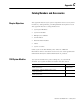
Motor Series: Brake Option:
Brake Response Time
Pickup/Dropout
mSec
1326AB-B5 K5 150/25
1326AB-B7 K7 120/30
1326AS-B6 K6 114/11
1326AS-B8 K8 200/12
MPL-B5 (460V) 4 70/50
MPL-B6 (460V) 4 200/120
MPL-B8 (460V) 4 250/200
MPL-B9 (460V) 4 300/200
24V DC
Power Supply
+ DC
DC com
CR6
10
9
Relay
Output 0
CR7
8
7
Relay
Output 1
CR8
6
5
Relay
Output 2
CR9
43
Relay
Output 3
1394 SERCOS Interface Control Board 1394C-SJT
xx
-D
CR9
CR8
CR7
CR6
TB1
TB2
Axis 0 Axis 1 Axis 2 Axis 3
TB1
TB2
TB1
TB2
TB1
TB2
I >1A
I >1A
I >1A
I >1A
1 2
3 4
Motor Brake
1 2 3 4
1 2 3 4
1 2
3 4
1 2 3 4
1 2
3 4
1 2 3 4
1 2
3 4
1394C-AM
xx
Motor brake
filter (Series C)
Brake current rated
greater than 1.0A
1394C-AM
xx
Motor brake
filter (Series C)
Brake current rated
greater than 1.0A
1394C-AM
xx
Motor brake
filter (Series C)
Brake current rated
greater than 1.0A
1394C-AM
xx
Motor brake
filter (Series C)
Brake current rated
greater than 1.0A
1 2
1 21 2 1 2