
Installation manual


Publication 1394-IN002B-EN-P — February 2004
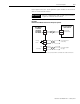
B-8 Interconnect Diagrams
In the figure below, the 1394 axis module is shown connected to
1326AS (460V) servo motors.
Figure B.8
Axis Module to 1326AS Motors Interconnect Diagram
TB1
TB2
43214321
PE2
W1
V1
U1
PE1
PE3
8321
T3T2T1
PE
79 456
B2 B1K2 K1
S2
S4
S1
S3
R1
R2
BLACK
RED
1
2
3
4
10
11
BLACK
WHITE
A
B
D
E
GREEN
BLACK
G
H
4.0 mm
2
(12 AWG)
A
12
13
TS+
TS-
Motor Feedback
Connector
(System Module)
Axis Module
Cable Clamp
Note 6
1326AS (460V) SERVO MOTORS
WITH RESOLVER FEEDBACK
1326-CCU-xxx Feedback Cable
Note 14
System Module
Cable Clamp
Note 6
Three-Phase
Motor Power
Ground
Motor Feedback
Thermostat
Brake
1326-CPx1-xxx
Motor Power Cable
Note 14
Thermostat and Brake Noise Filtering
Note 12
Motor Power
Terminal Blocks
Refer to Thermal Switch and Brake
Interconnect Diagrams beginning on
page B-9 for connections.
To
System Module
Single Point
Bond Bar
1394 AXIS MODULE
1394C-AMxx-xx
TERMINATOR CONNECTED TO
LAST AXIS MODULE
SLIDER INTERCONNECT
TO ADDITIONAL AXIS MODULES
Motor Brake
Filter (Series C)
Motor Thermal Switch
Filter (Series C)
LOGIC POWER
& SIGNALS
DC BUS POS.
DC BUS NEG.
SLIDER INTERCONNECT