MSVMASTER - - http://www.msvmaster.lv Model AM2 Installation Guide NOTE: This product is intended for installation by a professional installer only! Any attempt to install this product by any person other than a trained professional may result in severe damage to a vehicle’s electrical system and components. MSVMASTER - © 2007 Directed Electronics, Vista, CA N2102A 2007-06 - http://www.msvmaster.
MSVMASTER - - http://www.msvmaster.lv Code Hopping®, Doubleguard®, ESP®, FailSafe®, Ghost Switch®, Learn Routine™, Nite-Lite®, Nuisance Prevention® Circuitry, NPC®, Revenger®, Silent Mode™, Soft Chirp®, Stinger®, Valet®, Vehicle Recovery System®, VRS®, and Warn Away® are all Trademarks or Registered Trademarks of Directed Electronics, Inc. www.directechs.com DirectFax 800-999-1329 Technical Support 800-753-0800 These resources are for authorized Directed Dealer use only. MSVMASTER - - http://www.
MSVMASTER - - http://www.msvmaster.lv Table of Contents primary harness (H1), 12-pin connector . . . . . . . . . . . . . . . . . . . . . . . . . . . . . . . . . . . . . . . . . . .4 Peripheral Plug-In Harnesses . . . . . . . . . . . . . . . . . . . . . . . . . . . . . . . . . . . . . . . . . . . . . . . . . . . .9 Integrated LED/Valet® Switch, 2-Pin BLUE Plug . . . . . . . . . . . . . . . . . . . . . . . . . . . . . . . . .9 Super Bright LED, 2-Pin WHITE Plug . . . . . . . . . . . . . . . . . . . . . . .
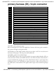
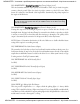
MSVMASTER - - http://www.msvmaster.lv primary harness (H1), 12-pin connector H1/1 ___ RED H1/2 ___ BLUE H1/3 ___ BLACK/WHITE-1 H1/4 ___ BLACK/WHITE H1/5 ___ GREEN/BLACK H1/6 ___ WHITE/BLACK H1/7 ___ VIOLET/BLACK H1/8 ___ BLUE/BLACK H1/9 ___ VIOLET H1/10 ___ WHITE (+/-) PARKING LIGHT FLASH OUTPUT H1/11 ___ BLACK (-) CHASSIS GROUND INPUT H1/12 ___ BROWN H1/13 ___ LT.
MSVMASTER - - http://www.msvmaster.lv H1/3 BLACK/WHITE-1 Domelight Supervision/Aux Channel 2 Input (pin 87) This wire determines what the output polarity of H1/4 will be. If the door pin circuit is negative, connect to chassis ground. If the door circuit is positive, connect to a fused 12V source. When feature 15 is selected to Aux Channel 2, this input will be determined by the polarity required on the output of the H1/4 wire. IMPORTANT! The H1/3 wire is not required for wiring the door locks.
MSVMASTER - - http://www.msvmaster.lv H1/11 BLACK (-) Chassis Ground Connection Connect this wire to a clean, paint-free sheet metal location (driver kick panel) using a factory bolt that DOES NOT have any vehicle component grounds attached to it. A screw should only be used when in conjunction with a two-sided lock washer. Under dash brackets and door sheet metal are not acceptable ground points. It is recommended that all security components be grounded at the same location.
MSVMASTER - - http://www.msvmaster.lv H1/14 WHITE/BLUE (-) Channel 3 Output This wire provides a (-) 200 mA output whenever the transmitter code controlling Channel 3 is received. This output will continue as long as that transmission is received. Use for options such as Directed’s 561T Valet® Start system, 529T or 530T power window controllers, etc.
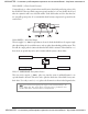
MSVMASTER - - http://www.msvmaster.lv H1/16 ORANGE (-) 500mA Ground-When Armed Output This wire supplies a (-) 500mA ground as long as the system is armed. This output ceases as soon as the system is disarmed. Note: If using the H1/16 Orange wire to activate an add-on accessory such as window automation, pager or voice module a 1-Amp diode must be installed to ensure proper operation. Insert the diode as shown in the following diagram. H1/17 BROWN/BLACK Unlock #87A Normally Closed See H1/5.
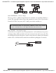
MSVMASTER - - http://www.msvmaster.lv Peripheral Plug-In Harnesses Integrated LED/Valet® Switch, 2-Pin BLUE Plug The integrated LED/Valet® switch should be accessible from the driver’s seat. It plugs into the BLUE port on the side of the unit. Consider how the button will be used before choosing a mounting location. Check for rear clearance before drilling a 5/16-inch hole and mounting the button. The integrated LED/Valet® switch requires an 1-1/2 inches of rear clearance for mounting.
MSVMASTER - - http://www.msvmaster.lv 3. Transmit. The transmitter is used to select the desired setting. As shipped, the unit is configured to the LED ON/1 chirp settings. These are the default settings. Pressing the lock button will move settings back to the LED ON/1 chirp setting. The LED will light solid (stop flashing) to indicate the setting. The horn will honk once (if connected). Pressing the unlock button will change the setting to the LED OFF setting.
MSVMASTER - - http://www.msvmaster.
MSVMASTER - - http://www.msvmaster.lv 1 ACTIVE/PASSIVE/AUTO REARM ARMING: When active arming is selected, the system will only arm when the transmitter is used. When set to passive, the system will arm automatically 30 seconds after the ignition is turned off. When set to auto rearm, the system will not arm by itself when the ignition is turned off but will rearm 30 seconds after being disarmed by the remote if the ignition was never turned on indicating the vehicle was never entered.
MSVMASTER - - http://www.msvmaster.lv 11 SECURITY FEATURES: When selected OFF, the (-) ground-when-armed and ignition sense trigger will not be active upon locking the vehicle. When selected ON, (-) ground-when-armed output will be active and can be used to operate a starter kill. The unit will also trigger a panic sequence if the ignition is turned on before unlocking/disarming the system.
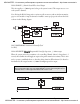
MSVMASTER - - http://www.msvmaster.lv 2. Choose. Within 10 seconds, press and release the Valet/program switch the number of times corresponding to the desired channel listed below. Once you have selected the channel, press the switch once more and HOLD it. The LED will flash and the horn will honk ( if connected) to confirm the selected channel. Do not release the Valet/program switch. 3. Transmit.
MSVMASTER - - http://www.msvmaster.lv Transmitter Configurations The transmitters can be programmed with the standard or single button arm/disarm configurations by using the Auto Learn functions in the Transmitter/Receiver Learn Routine. Standard Configuration A remote that uses the standard configuration operates similarly to many factory keyless entry remotes. A standard configuration transmitter allows lock/arm, unlock/disarm, and Panic Mode activation with separate buttons.
MSVMASTER - - http://www.msvmaster.lv Programming Master Dealer Remotes Follow the program instructions above and use the Directed part number 465D(master dealer remote). The only programming channels in master dealer mode are channel 1 and 8. CHANNEL NUMER FUNCTION 1 Auto Learn 8 Delete all transmitters Rapid Resume Logic Rapid Resume Logic ensures that the when the system is powered up it will return to the same state it was in when power is disconnected.
© MSVMASTER - 2007 Directed Electronics LIGHT FLASH JUMPER Valet/LED Switch VIOLET Unlock #87 Normally Open (Input) RED/WHITE (-) Channel output 2 / Domelight supervision BLUE/BLACK Unlock #30 Common Output BROWN/BLACK Unlock #87A Normally Closed VIOLET/BLACK Lock #87 Normally Open (Input) ORANGE (-) 500 mA Ground-When-Armed Output WHITE/BLACK Lock #87A Normally Closed YELLOW (+) Switched Ignition Input GREEN/BLACK Lock #30 Common Output WHITE/BLUE (-) 200 mA Channel 3 Validity Output BLACK/WHITE Outpu