AM15 DISHWASHER TECHNICAL MANUAL 208-240V/60/3 SPECIFICATION SHEET INSTALLATION INSTRUCTIONS OPERATION INSTRUCTIONS CLEANING INSTRUCTIONS MAINTENANCE INSTRUCTIONS TROUBLE SHOOTING INSTRUCTIONS WIRING DIAGRAMS CATALOG OF REPLACEMENT PARTS SMARTPARTS™ USER GUIDE RECOMMENDED SPARE PARTS LIST
Need other Hobart Services? • Warranty Registration • Delivery and Installation • Preventive Maintenance • Hobart Service Contracts • Extended Warranty Contracts • Parts and Accessories • Specialty Programs • Water Treatment Programs AM15 Dishwasher Technical Manual Page 2 of 83
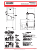
Item #______________________________________ Quantity____________________________________ C.S.I. Section 11400 AM SELECT DISHWASHER 701 S Ridge Avenue, Troy, OH 45374 1-888-4HOBART • www.hobartcorp.com STANDARD FEATURES MODEL ■ .
AM SELECT DISHWASHER – ELECTRIC Page 2 of 8 701 S Ridge Avenue, Troy, OH 45374 1-888-4HOBART • www.hobartcorp.
701 S Ridge Avenue, Troy, OH 45374 1-888-4HOBART • www.hobartcorp.
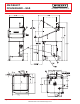
AM SELECT DISHWASHER – GAS Page 4 of 8 701 S Ridge Avenue, Troy, OH 45374 1-888-4HOBART • www.hobartcorp.
01 S Ridge Avenue, Troy, OH 45374 1-888-4HOBART • www.hobartcorp.
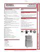
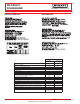
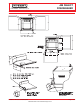
AM SELECT DISHWASHER 701 S Ridge Avenue, Troy, OH 45374 1-888-4HOBART • www.hobartcorp.com ELECTRIC TANK HEAT GAS TANK HEAT AM Select Hot Water Sanitizing Chemical Sanitizing Dishes per Hour (Average 25 per rack) 58 1,450 65 1,625 Glasses per Hour (Average 45 per rack) 2,610 2,925 251⁄4" 251⁄4" Machine Ratings (Mechanical) Racks per Hour (Max.) Table to Table - Inside Tank at Table Connection (Inches) Overall Dimensions - (H x W x D) (Inches) Wash Motor H.P.
701 S Ridge Avenue, Troy, OH 45374 1-888-4HOBART • www.hobartcorp.
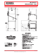
AM SELECT DISHWASHER 701 S Ridge Avenue, Troy, OH 45374 1-888-4HOBART • www.hobartcorp.com The microcomputer-based control system is built into the AM Select dishwasher. It is available in standard electrical specifications of 208-240/60/1, 208-240/60/3, 480/60/3, 200-240/50/3, 380-415/50/3 and is equipped with a reduced voltage pilot circuit transformer.
AM Select DISHWASHERS MODELS AM15 AM15F AM15T ML-130038 ML-130045 ML-130039 701 s. RIDGE AVENUE TROY, OHIO 45374-0001 937 332-3000 www.hobartcorp.com AM15 Dishwasher Technical Manual Page 11 of 83 FORM 35320 Rev. C (Oct.
post in a prominent location the instructions to be followed in the event the smell of gas is detected. This information can be obtained from the local gas supplier. important in the event a gas odor is detected, shut down unit(s) at main shutoff valve and contact the local gas company or gas supplier for service. for your safety do not store or use gasoline or other flammable vapors or liquids in the vicinity of this or any other appliance. Model AM15 Model AM15F Pressure Gauge Fig.
Table of Contents GENERAL. . . . . . . . . . . . . . . . . . . . . . . . . . . . . . . . . . . . . . . . . . . . . . . . . . . . . . . . . . . . . . . . . . . 4 INSTALLATION. . . . . . . . . . . . . . . . . . . . . . . . . . . . . . . . . . . . . . . . . . . . . . . . . . . . . . . . . . . . . . . 5 UNPACKING. . . . . . . . . . . . . . . . . . . . . . . . . . . . . . . . . . . . . . . . . . . . . . . . . . . . . . . . . . . . . . . 5 INSTALLATION CODES . . . . . . . . . . . . . . . . . . . . . . . . . . . .
Installation, Operation, and Care of AM Select DISHWASHERS SAVE THESE INSTRUCTIONS GENERAL Models AM15 and AM15T dishwashers can be configured for straight through or corner operation. Model AM15F is configured for front loading. AM15 and AM15T dishwashers are shipped from the factory in straight-through configuration. Straight-through machines can easily be converted to corner operation. Model AM15F includes a front-loader shelf and left- and right-side shields as standard equipment.
INSTALLATION UNPACKING Immediately after unpacking the dishwasher, check for possible shipping damage. If this machine is found to be damaged, save the packaging material and contact the carrier within 15 days of delivery. Prior to installation, test the electrical service to make sure it agrees with the specifications on the machine data plate; this includes the optional electric booster, if equipped. The dishwasher data plate is located at the bottom of the front panel.
CORNER INSTALLATION Before placing the dishwasher in its operating location, check machine configuration. If the machine is being installed in a corner (Figs. 4, 5), clearances of 20 inches out from the dishwasher under the left-hand tabling by 27 inches above the finished floor and 15 inches out from the dishwasher at the right side by 27 inches above the finished floor must be provided for servicing.
A splash shield is available (at extra cost) for corner installations to cover the left side opening to the wall. Install the splash shield on the left side using the two 1⁄4-20 studs on the left rear corner with a lockwasher and nut for each (Fig. 8) and using the two 1⁄4-20 bolts, lockwashers and nuts on the left front corner (fasteners are provided in the kit).
PLUMBING CONNECTIONS WARNING: PLUMBING CONNECTIONS MUST COMPLY WITH APPLICABLE SANITARY, SAFETY AND PLUMBING CODES. DRAIN CONNECTION The drain connection is a 11⁄ 2" externally threaded pipe connected straight down from the bottom of the wash tank (Fig. 10). The connection can be made in any direction by using the proper fitting (not supplied) and routing to the appropriate drain line. If a grease trap is required by code, it should have a minimum flow capacity of 38 gallons per minute. Fig.
GAS TANK HEAT (When Specified) Check the gas data plate attached to the dishwasher or the tag attached to the incoming gas piping for the type of gas to be used. GAS PRESSURE SPECIFICATION The burner is not adjustable. The maximum [FLOWING GAS PRESSURE — NOT STATIC] flowing inlet gas pressure must not exceed Inches W.C. (Water Column) FLOWING Type the Maximum value in the table.
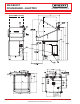
VENTING REQUIREMENTS — WITH GAS TANK HEAT Hobart model AM15, AM15F or AM15T dishwashers equipped for gas tank heat are not provided with a flue collar and are not intended to have the flue directly connected to a ventilation system. However, the products of combustion must be vented to the outside air. The most common method of venting is a vent hood over the entire dishwasher (Fig. 12). Refer to Rate of Exhaust Flow Calculations on the next page for calculations of the proper vent rate for your hood.
➤ LENGTH ➤ ➤ RATE OF EXHAUST FLOW CALCULATIONS ➤ CLEARANCE HEIGHT ➤ NOTE: Any listed and labeled factory-built commercial exhaust hood tested in accordance with UL Standard 710 by a nationally recognized testing laboratory, should be installed according to the terms of its listing and the manufacturer’s installation instructions. Based on the 1996 International Mechanical Code. The Rate of air flow required for a vent hood is calculated using the following definitions (Fig.
ELECTRICAL CONNECTIONS WARNING: ELECTRICAL AND GROUNDING CONNECTIONS MUST COMPLY WITH THE APPLICABLE PORTIONS OF THE NATIONAL ELECTRICAL CODE AND/OR OTHER LOCAL ELECTRICAL CODES. WARNING: DISCONNECT THE ELECTRICAL POWER TO THE MACHINE (BOTH DISHWASHER AND BOOSTER IF APPLICABLE) AND FOLLOW LOCKOUT / TAGOUT PROCEDURES. Refer to the wiring diagram attached inside the front trim panel and to the machine data plate for service size requirements when connecting the dishwasher.
Dishwasher With Electric Booster (Separately Connected) Single phase machines with an electric booster require two separate connections, one for the booster and the other for the dishwasher (including motor, controls and tank heat). For single-phase machines, all power supply connections are made to terminal blocks (Fig. 16). The single phase dishwasher is connected to terminal block 1TB in the controls area. The single phase booster is connected to terminal block 2TB in the controls area.
DETERGENT, RINSE AID, SANITIZER DISPENSERS — Tubing Installation Detergent, rinse aid and / or sanitizer dispensers (not provided by Hobart) must have all connections sealed against leakage. The dishwasher uses 0.74 gallons of rinse water per rack at a flow rate of 4.4 gallons per minute at 20 psig flowing pressure (equivalent to a maximum head pressure of 46 feet of water). This information is used when setting the detergent, rinse aid or sanitizer pumps.
Equipment Connections — Detergent, Rinse Aid, Sanitizer Dispensers WARNING: ELECTRICAL AND GROUNDING CONNECTIONS MUST COMPLY WITH THE APPLICABLE PORTIONS OF THE NATIONAL ELECTRICAL CODE AND/OR OTHER LOCAL ELECTRICAL CODES. WARNING: DISCONNECT THE ELECTRICAL POWER TO THE MACHINE (BOTH DISHWASHER AND BOOSTER IF APPLICABLE) AND FOLLOW LOCKOUT / TAGOUT PROCEDURES.
SETUP (All Models) Sanitizing Mode • With the machine OFF, press the ON key. • Immediately press and hold the OFF key. SET H °C SET C °C P °C °F The display initializes until 88 displays. Next, SET X °F °C displays. X can be H, C or P: H = Hot Water Sanitizing, Internal Booster. C = Chemical Sanitizing, No Booster. P = Hot Water Sanitizing, External Booster. SET °F °F • Press CYCLE to select P, H, or C as the sanitizing mode.
OPERATION PREPARATION The overflow tube must be in its proper location below the strainer pan (Fig. 23). Place the strainer pan and the strainer bucket in their proper positions (Fig. 24). Fig. 24 Fig. 23 An automatic detergent dispenser is recommended. Closely follow supplier’s instructions. Close the door; this will automatically close the drain. Open the manual gas valve (if applicable). Press the ON button to turn the power on (Fig. 25).
DISHWASHING Scrape the dishes to remove large particles of food and debris. Never use steel wool on ware to be loaded into the dishmachine. Fig. 26 Arrange the dishes in a rack. Do not stack dishes one on top of another, as water must have free access to all sides of every dish. Stand plates and dishes up edgewise in a peg-type rack (Fig. 26). Cups, glasses, and bowls should be inverted in an open-type or compartment type rack (Fig. 26).
CLEANING The machine must be thoroughly cleaned at the end of each working shift or at least daily. Never use steel wool to clean warewasher surfaces. Use only products formulated to be safe on stainless steel. 1. Push the OFF button. 2. Open the machine door. 3. Clean off the dish tables into the dishwasher. 4. Drain the machine by lifting up the drain lever (Fig. 27). 5. Thoroughly cleanse and flush the dishwasher interior. Remove remaining soil with a soft cloth or brush and mild cleanser. Rinse again.
DELIME INSTRUCTIONS If the optional delime notification is activated and the DELIME light is on, follow the instructions, below. Delime is also necessary if deposits are visible inside or outside the machine. DELIME INSTRUCTIONS 1. Remove rack, drain tank, press “OFF”. 2. Press and hold “Cycle” & “ON” for 3 seconds; close door, unit fills then indicates “ADD DELIME”. 3. Open door & add delime agent per supplier instructions for 14 gallon tank. 4. Close door, pump starts & display flashes “DELIME”.
MAINTENANCE WARNING: DISCONNECT THE ELECTRICAL POWER TO THE MACHINE (BOTH DISHWASHER AND BOOSTER IF APPLICABLE) AND FOLLOW LOCKOUT / TAGOUT PROCEDURES. Wash Arms Upper and lower wash and rinse arms (Figs. 28, 29) should turn freely and continue turning for a few seconds after being whirled by hand. To check, DISCONNECT ELECTRICAL POWER SUPPLY (BOTH DISHWASHER AND BOOSTER IF APPLICABLE), rotate arms and remove any obstructions causing improper operation.
TROUBLESHOOTING Manual Reset Button on Pump Motor If the pump motor becomes overheated, the thermal overload protector will cause the motor to not operate. If this occurs, contact Service. To avoid a service call, check symptoms and related possible causes. If machine still does not operate properly, contact Service. SYMPTOM POSSIBLE CAUSE No machine operation. 1. Machine off, turn machine on. 2. Blown fuse or tripped circuit breaker at power supply. 3. Check tank water level. Dishes not clean. 1.
SYMPTOM POSSIBLE CAUSE Inadequate rinse or rinse 1. water temperature too low. Possible EE display. 2. 3. Dirty line strainer causing reduced water flow. Turn off water supply, remove strainer cap, withdraw and clean screen. Reassemble. Low supply line pressure. Excessive mineral deposits throughout wash and rinse system. Deliming may be necessary, refer to page 20. 4. Incoming water temperature to booster (if applicable) below 110°F.
SERVICE Contact your local Hobart-authorized service office for any repairs or adjustments needed on this equipment. If a gas orifice fitting is to be replaced, have it serviced by qualified Hobart-authorized service personnel. Long-term service contracts are available on this and other Hobart products. Call 1-888-4HOBART for Hobart Service 24 hours a day. FORM 35320 Rev. C (Oct. 2009) Printed in U.S.A.
3CON L1 YEL BLU T1 L2 SERVICE CONNECTION L3 2CON L1 T3 L2 YEL BRN BRN BLU T2 BLK BSTR HTR RED YEL T1 BLK SERVICE CONNECTION BLU RED T2 L3 T3 BLK BLK 1CON L1 T1 BLK BLK L2 T2 BLK BLK L3 T3 BLK TANK HTR BLU YEL L1 L2 WARNING ELECTRICAL AND GROUNDING CONNECTIONS MUST COMPLY WITH THE APPLICABLE PORTIONS OF THE NATIONAL ELECTRICAL CODE AND/OR OTHER LOCAL ELECTRICAL CODES PUMP MTR L3 3TB BLK BLK H1 H2 H3 H4 4 1CR 2 BLK DPS1 BLK DPS2 BLK RPS1 MAX LOAD 1.
3TB 2T DISPLAY J4 J3 1T POWER J1 J13 J11 CONTROL BOARD J7 1CR J6 J10 J15 J2 J9 J3 RELAY J1 F1 F2 K8 NO C NC BOARD C K6 NO C J11 K5 NO 1 CON C1 C3 2 CON C1 C3 3 CON OPT C1 C3 1TB (SPEC OPTION) LEGEND TEST PINS = TEST PAD = SWITCH = LED = CONTROL BOARD AM15 Dishwasher Technical Manual Page 36 of 83 AI2695
CA TALOG OF AT REPLACEMENT PAR TS ARTS DISHW ASHER DISHWASHER AM15 AM15T AM15F A product of HOBART 701 S.
AM15 SERIES DISHW ASHER REPLACEMENT P AR TS DISHWASHER PAR ARTS F-43094 (October 2004) - 2 - AM15 Dishwasher Technical Manual Page 38 of 83 © HOBART
AM15 SERIES DISHW ASHER REPLACEMENT P AR TS DISHWASHER PAR ARTS Table of Contents 5 7 9 11 13 15 17 19 21 23 25 27 29 31 32 33 35 36 CONTROLS CONTROL BOX (ELECTRIC HEAT) CONTROL BOX (GAS HEAT) MOTOR AND PUMP UPPER WASH ARM LOWER WASH ARM INSIDE PIPING AND OUTSIDE RINSE PIPING (W/O BOOSTER) INSIDE PIPING AND OUTSIDE RINSE PIPING (W/BOOSTER) ELECTRIC BOOSTER TANK LOW WATER PROTECTION AND ELECTRIC HEAT DRAIN UNIT DOOR ASSEMBLY (AM15) DOOR ASSEMBLY (AM15T & AM15F) PANELS AND RACK SUPPORT FRONT TRAY (AM15F) GA
AM15 SERIES DISHW ASHER REPLACEMENT P AR TS DISHWASHER PAR ARTS 3 2 1 4 28 5 27 6 7 8 9 10 11 29 26 25 12 19 13 24 23 14 18 15 22 21 20 17 16 PL-57404 CONTROLS F-43094 (October 2004) - 4 - AM15 Dishwasher Technical Manual Page 40 of 83
AM15 SERIES DISHW ASHER REPLACEMENT P AR TS DISHWASHER PAR ARTS CONTROLS ILLUS. PL-57404 1 2 3 4 5 6 7 8 9 10 11 12 13 14 15 16 17 18 19 20 21 22 23 24 25 26 27 28 29 PAR T NO.
AM15 SERIES DISHW ASHER REPLACEMENT P AR TS DISHWASHER PAR ARTS 6 3 5 10 4 11 9 12 7 8 1 13 2 14 46 42 40-41 44 16 45 15 17 43 18 20 21 19 22 39 36 37 23 38 24 25 SINGLE PHASE ONLY 26 35 34 33 32 28 31 29 27 ELECTRIC HEAT W/SPEC ONLY PL-57403 30 CONTROL BOX (ELECTRIC HEA T) HEAT) F-43094 (October 2004) - 6 - AM15 Dishwasher Technical Manual Page 42 of 83
AM15 SERIES DISHW ASHER REPLACEMENT P AR TS DISHWASHER PAR ARTS CONTROL BOX (ELECTRIC HEA T) HEAT) ILLUS. PL-57403 1 2 3 4 5 6 7 8 9 10 11 12 13 14 15 16 17 18 19 20 21 22 23 24 25 26 27 28 29 30 31 32 33 34 35 36 37 38 39 40 41 42 43 44 45 46 PAR T NO.
AM15 SERIES DISHW ASHER REPLACEMENT P AR TS DISHWASHER PAR ARTS 6 3 5 10 4 11 9 12 7 8 1 13 2 14 37 35 16 36 33 15 34 17 18 29 30 19 32 31 20 28 21 27 26 22 23 25 24 PL-57414 CONTROL BOX (GAS HEA T) HEAT) F-43094 (October 2004) - 8 - AM15 Dishwasher Technical Manual Page 44 of 83
AM15 SERIES DISHW ASHER REPLACEMENT P AR TS DISHWASHER PAR ARTS CONTROL BOX (GAS HEA T) HEAT) ILLUS. PL-57414 1 2 3 4 5 6 7 8 9 10 11 12 13 14 15 16 17 18 19 20 21 22 23 24 25 26 27 28 29 30 31 32 33 34 35 36 37 PAR T NO.
AM15 SERIES DISHW ASHER REPLACEMENT P AR TS DISHWASHER PAR ARTS 1 2 3 9 8 28 7 4 5 27 6 26 10 25 12 11 24 15 13 14 23 16 17 18 19 20 21 PL-57402 22 MOT OR AND PUMP MOTOR F-43094 (October 2004) - 10 - AM15 Dishwasher Technical Manual Page 46 of 83
AM15 SERIES DISHW ASHER REPLACEMENT P AR TS DISHWASHER PAR ARTS MOT OR AND PUMP MOTOR ILLUS. PL-57402 1 2 3 4 5 6 7 8 9 10 11 12 13 14 15 16 17 18 19 20 21 22 23 24 25 26 27 28 PAR T NO.
AM15 SERIES DISHW ASHER REPLACEMENT P AR TS DISHWASHER PAR ARTS 1 2 3 4 5 6 7 8 9 10 11 12 13 14 PL-57399 UPPER W ASH ARM WASH F-43094 (October 2004) - 12 - AM15 Dishwasher Technical Manual Page 48 of 83
AM15 SERIES DISHW ASHER REPLACEMENT P AR TS DISHWASHER PAR ARTS UPPER W ASH ARM WASH ILLUS. PL-57399 1 2 3 4 5 6 7 8 9 10 11 12 13 14 PAR T NO. ART SC-125-20 00-067500-00110 00-893031 00-067500-00117 SC-055-01 00-893052 00-893033 BA-002-40 00-286947 00-067500-00019 00-893007 SC-066-06 00-893093-00001 00-893093-00002 00-893008 NAME OF P AR T PAR ART AMT AMT.. Cap Screw 5/16-18 x 3/8 Hex Hd. ............................................................................................. 2 O-Ring ..........
AM15 SERIES DISHW ASHER REPLACEMENT P AR TS DISHWASHER PAR ARTS 1-2 3 4 5 7 6 8 9 10 16 15 11 12 14 13 LOWER W ASH ARM WASH F-43094 (October 2004) - 14 - AM15 Dishwasher Technical Manual Page 50 of 83 PL-57401
AM15 SERIES DISHW ASHER REPLACEMENT P AR TS DISHWASHER PAR ARTS LOWER W ASH ARM WASH ILLUS. PL-57401 1 2 3 4 5 6 7 8 9 10 11 12 13 14 15 16 PAR T NO. ART 00-893032 00-893032-00002 SC-066-06 00-893093-00001 00-893093-00002 00-893007 00-067500-00019 00-286947 BA-002-40 00-893033 00-893052 00-893044 00-893030 00-067500-00110 00-067500-00117 SC-055-01 00-893008 NAME OF P AR T PAR ART AMT AMT.. Tube – Wash (AM15) ..............................................................................................
AM15 SERIES DISHW ASHER REPLACEMENT P AR TS DISHWASHER PAR ARTS 4-5 6 3 2 1 7 8-9-10 25 11 30 29 12 24 23 22 13 14 28 26-27 21 15 THRU 18 19 20 PL-57407 INSIDE PIPING AND OUTSIDE RINSE PIPING (W/O BOOSTER) F-43094 (October 2004) - 16 - AM15 Dishwasher Technical Manual Page 52 of 83
AM15 SERIES DISHW ASHER REPLACEMENT P AR TS DISHWASHER PAR ARTS INSIDE PIPING AND OUTSIDE RINSE PIPING (W/O BOOSTER) ILLUS. PL-57407 1 2 3 4 5 6 7 8 9 10 11 12 13 14 15 16 17 18 19 20 21 22 23 24 25 26 27 28 29 30 PAR T NO.
AM15 SERIES DISHW ASHER REPLACEMENT P AR TS DISHWASHER PAR ARTS 4-5 7 3 2 6 1 8 19 9 18 13 12 11 17 14 15-16 10 PL-57408 INSIDE PIPING AND OUTSIDE RINSE PIPING (W/BOOSTER) F-43094 (October 2004) - 18 - AM15 Dishwasher Technical Manual Page 54 of 83
AM15 SERIES DISHW ASHER REPLACEMENT P AR TS DISHWASHER PAR ARTS INSIDE PIPING AND OUTSIDE RINSE PIPING (W/BOOSTER) ILLUS. PL-57408 1 2 3 4 5 6 7 8 9 10 11 12 13 14 15 16 17 18 19 PAR T NO. ART WL-006-23 NS-036-19 00-893054 00-292909 00-292910 00-328994 00-328247 00-893059 FP-015-16 00-893444-00002 NS-015-11 WL-006-23 FE-022-84 00-893053 00-893038-00001 00-893038-00004 SC-041-12 00-276407 00-067500-00012 NAME OF P AR T PAR ART AMT AMT.. Lockwasher 5/16 Helical ..........................................
AM15 SERIES DISHW ASHER REPLACEMENT P AR TS DISHWASHER PAR ARTS 13 12 11 8 10 7 9 4-5-6 3 2 1 16 40 17 39 35 38 15 34 14 37 41 42 36 33 32 31 18 THRU 21 28-29-30 27 22 26 23 25 24 ELECTRIC BOOSTER TANK F-43094 (October 2004) - 20 - AM15 Dishwasher Technical Manual Page 56 of 83 PL-57400
AM15 SERIES DISHW ASHER REPLACEMENT P AR TS DISHWASHER PAR ARTS ELECTRIC BOOSTER TANK ILLUS. PL-57400 1 2 3 4 5 6 7 8 9 10 11 12 13 14 15 16 17 18 19 20 21 22 23 24 25 26 27 28 29 30 31 32 33 34 35 36 37 38 39 40 41 42 PAR T NO.
AM15 SERIES DISHW ASHER REPLACEMENT P AR TS DISHWASHER PAR ARTS 5-6-7 4 8 3 9 10 2 1 11 12 13 17 21 19 18 14 20 23 15 22 16 LOW W ATER PROTECTION AND ELECTRIC HEA T WA HEAT F-43094 (October 2004) - 22 - AM15 Dishwasher Technical Manual Page 58 of 83 PL-57405
AM15 SERIES DISHW ASHER REPLACEMENT P AR TS DISHWASHER PAR ARTS LOW W ATER PROTECTION AND ELECTRIC HEA T WA HEAT ILLUS. PL-57405 1 2 3 4 5 6 7 8 9 10 11 12 13 14 15 16 17 18 19 20 21 22 23 PAR T NO.
AM15 SERIES DISHW ASHER REPLACEMENT P AR TS DISHWASHER PAR ARTS 1 3 11 2 4 10 9 6 12 5 8 7 PL-57409 DRAIN UNIT F-43094 (October 2004) - 24 - AM15 Dishwasher Technical Manual Page 60 of 83
AM15 SERIES DISHW ASHER REPLACEMENT P AR TS DISHWASHER PAR ARTS DRAIN UNIT ILLUS. PL-57409 1 2 3 4 5 6 7 8 9 10 11 12 PAR T NO. ART 00-893045 NS-047-82 00-119116 00-893091 00-893095 SC-066-06 00-067500-00120 00-893071 00-893072 WS-019-33 SD-038-84 00-118999 NAME OF P AR T PAR ART AMT AMT.. Strainer Pan ............................................................................................................................... 1 Stop Nut 1/4-20 Hex (SST) ..............................................
AM15 SERIES DISHW ASHER REPLACEMENT P AR TS DISHWASHER PAR ARTS 13 9 6 7 12 8 14 5 10 11 4 18 3 19 2 20 15 1 16 17 21 22 42 24 23 25 26 27 41 28 29 40 31 33 36 39 38 35 32 34 37 PL-57413 DOOR ASSEMBL Y (AM15) ASSEMBLY F-43094 (October 2004) 30 - 26 - AM15 Dishwasher Technical Manual Page 62 of 83
AM15 SERIES DISHW ASHER REPLACEMENT P AR TS DISHWASHER PAR ARTS DOOR ASSEMBL Y (AM15) ASSEMBLY ILLUS. PL-57413 1 2 3 4 5 6 7 8 9 10 11 12 13 14 15 16 17 18 19 20 21 22 23 24 25 26 27 28 29 30 31 32 33 34 35 36 37 38 39 40 41 42 PAR T NO.
AM15 SERIES DISHW ASHER REPLACEMENT P AR TS DISHWASHER PAR ARTS 3 2 13 4 5 6 8 1 10 12 9 11 14 15 7 25 24 23 16 22 26 27 54 17 28 30 29 18 31 52 32 19 33 21 34 20 35 53 42 51 41 36 39 38 43 50 37 40 49 48 44 47 46 45 PL-57412 DOOR ASSEMBL Y (AM15T & AM15F) ASSEMBLY F-43094 (October 2004) - 28 - AM15 Dishwasher Technical Manual Page 64 of 83
AM15 SERIES DISHW ASHER REPLACEMENT P AR TS DISHWASHER PAR ARTS DOOR ASSEMBL Y (AM15T & AM15F) ASSEMBLY ILLUS. PL-57412 1 2 3 4 5 6 7 8 9 10 11 12 13 14 15 16 17 18 19 20 21 22 23 24 25 26 27 28 29 30 31 32 33 34 35 36 37 38 39 40 41 42 43 44 45 46 47 48 49 50 51 52 53 54 PAR T NO.
AM15 SERIES DISHW ASHER REPLACEMENT P AR TS DISHWASHER PAR ARTS 5 3 1-2 4 29 30 6 7 31 32 8 9 10 25 28 26 24 13 27 11 23 12 22 21 17 20 36 16 15 35 19 18 14 34 33 PANELS AND RACK SUPPOR T SUPPORT F-43094 (October 2004) - 30 - AM15 Dishwasher Technical Manual Page 66 of 83 PL-57406
AM15 SERIES DISHW ASHER REPLACEMENT P AR TS DISHWASHER PAR ARTS PANELS AND RACK SUPPOR T SUPPORT ILLUS. PL-57406 1 2 3 4 5 6 7 8 9 10 11 12 13 14 15 16 17 18 19 20 21 22 23 24 25 26 27 28 29 30 31 32 33 34 35 36 PAR T NO.
AM15 SERIES DISHW ASHER REPLACEMENT P AR TS DISHWASHER PAR ARTS 7 6 8 1 2 5 4 3 PL-57410 FRONT TRA Y (AM15F) TRAY ILLUS. PL-57410 1 2 3 4 5 6 7 8 PAR T NO. ART 00-893220 00-893096 00-893817 00-893815 00-893816 NS-047-82 SC-059-29 00-893983 F-43094 (October 2004) NAME OF P AR T PAR ART AMT AMT.. Bracket – Splash (Corner) ....................................................................................................... 2 Panel – Splash ........................................................
AM15 SERIES DISHW ASHER REPLACEMENT P AR TS DISHWASHER PAR ARTS 1-2 3 4 19 18 5-6 7 17 8 16 9 15 14 13 10 11 12 GAS HEA T PIPING HEAT ILLUS. PL-5741 1 PL-57411 1 2 3 4 5 6 7 8 9 10 11 12 13 14 15 16 17 18 19 PAR T NO.
AM15 SERIES DISHW ASHER REPLACEMENT P AR TS DISHWASHER PAR ARTS 42 1 2 3 43 41 40 39 38 37 36 33 32 35 12 13 11 34 10 31 28-29 5 6 30 27 7 26 8 25 24 14 9 15 23 22 16 17 18 20 19 PL-57415 21 GAS HEA T COMPONENTS HEAT F-43094 (October 2004) - 34 - AM15 Dishwasher Technical Manual Page 70 of 83 4
AM15 SERIES DISHW ASHER REPLACEMENT P AR TS DISHWASHER PAR ARTS GAS HEA T COMPONENTS HEAT ILLUS. PL-57415 1 2 3 4 5 6 7 8 9 10 11 12 13 14 15 16 17 18 19 20 21 22 23 24 25 26 27 28 29 30 31 32 33 34 35 36 37 38 39 40 41 42 43 PAR T NO.
AM15 SERIES DISHW ASHER REPLACEMENT P AR TS DISHWASHER PAR ARTS 2 1 PL-53023 DISH RACKS ILLUS. PL-53023 1 2 FORM 43094 PAR T NO. ART 00-315191 00-315193 00-295288 00-892671 00-474800 NAME OF P AR T PAR ART AMT AMT.. Rack – Peg (Packaged) ........................................................................................................... 1 Rack – Combination (Packaged) .............................................................................................
Online Parts Catalog User Guide Note: It is helpful, but not essential to know the ML (Material List) Number of the equipment for which a part is needed Section 1 – If Equipment ML Number is known Section 2 – If Equipment ML Number is not known AM15 Dishwasher Technical Manual Page 73 of 83
User Guide From hobartservice.
If the ML Number of the Equipment is known, select Use SmartParts Now (We’ll explain what to do if the ML number of the Equipment is not known in Section 2) Enter the ML number and click on Search SmartParts 104352 For this example, the part needed is a Water Pressure Gauge used on the LX 30 Undercounter Dishwasher 104352 The ML number of this dishwasher is 104352 AM15 Dishwasher Technical Manual Page 75 of 83 Section 1 – If Equipment ML Number is known This is SmartParts home page
• Then click on Continue The Water Pressure Gauge is on the Base Assembly Select Base Assembly Then click on Continue AM15 Dishwasher Technical Manual Page 76 of 83 Section 1 – If Equipment ML Number is known Click on the Radio button to select the Parts Catalog
Select an appropriate figure size Locate the part needed (Water Pressure Gauge) on the drawing 19: Gauge – Water Pressure (LX30/40, LXG, & LXiG Series) Placing the cursor on the number will display the Description of the Part Click on the number pointing to the part AM15 Dishwasher Technical Manual Page 77 of 83 Section 1 – If Equipment ML Number is known •
Selecting the part on the figure causes the part to be highlighted on the parts list • Click on the Add button to add the part to the shopping cart • You can add more parts or change the quantity of the parts already in the cart • When finished, click on the Confirm Parts Selected and then on Print Parts List if you want to print Use SMARTPARTS Now AM15 Dishwasher Technical Manual Page 78 of 83 Section 1 – If Equipment ML Number is known •
This (again) is SmartParts home page If the ML Number of the Equipment is not known, click on the Radio button to select Warewash / Waste Equipment Then click on Continue (Go to Section 1 if you do know the ML number of the Equipment) Click on the Radio button to select UnderCounter Dishwasher Then click on Continue AM15 Dishwasher Technical Manual Page 79 of 83 Section 2 – If Equipment ML Number is not known For this example, the part needed is a Water Pressure Gauge used on the LX 30 Undercounter Dis
Then click on Continue The Water Pressure Gauge is on the Base Assembly Select Base Assembly Then click on Continue AM15 Dishwasher Technical Manual Page 80 of 83 Section 2 – If Equipment ML Number is not known Click on the Radio button to select LX Series Dishwashers
Locate the part needed (Water Pressure Gauge) on the drawing 19: Gauge – Water Pressure (LX30/40, LXG, & LXiG Series) Placing the cursor on the number will display the Description of the Part Click on the number pointing to the part AM15 Dishwasher Technical Manual Page 81 of 83 Section 2 – If Equipment ML Number is not known Select an appropriate figure size
Selecting the part on the figure causes the part to be highlighted on the parts list • Click on the Add button to add the part to the shopping cart • You can add more parts or change the quantity of the parts already in the cart • When finished, click on the Confirm Parts Selected and then on Print Parts List if you want to print Use SMARTPARTS Now AM15 Dishwasher Technical Manual Page 82 of 83 Section 2 – If Equipment ML Number is not known •
AM15-2 DISHWASHER NOVEMBER 2009 PRODUCT SERVICE DEPARTMENT TROY, OH. 45374-0001 RECOMMENDED SPARE PARTS LIST AM15-2 DISHWASHER ELECTRIC TANK HEAT (208-240/60/3) Qty.