AM1 Security System installation guide © 2005 Directed Electronics, Inc.
NOTE: This product is intended for installation by a professional installer only! Any attempt to install this product by any person other than a trained professional may result in severe damage to a vehicle’s electrical system and components.
contents what is included . . . . . . . . . . . . . . . .3 control module . . . . . . . . . . . . . . . .3 installation points to remember . . .3 before beginning the installation: 4 after the install: . . . . . . . . . . . . . .4 tools required . . . . . . . . . . . . . . . . .4 deciding on component location . .5 control module . . . . . . . . . . . . . .5 integrated LED/Valet® switch . . . .6 starter kill relay . . . . . . . . . . . . . .6 connecting your wires . . . . . . . . . . .
ii © 2005 directed electronics, inc.
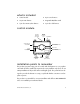
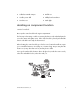
what is included z Control module z 4-pin sensor harness z 12-pin main harness z Integrated LED/Valet switch z 7-pin door monitor/Aux harness z 3-pin door lock harness control module OPTIONAL RECEIVER (NOT USED) DEALER MASTER CONTROL LOOP BITWRITER® SHOCK SENSOR ADJUSTMENT 7-PIN DOOR MONITOR/ AUX HARNESS DOOR LOCK 10-AMP FUSE/JUMPER ACCESS LED (INTEGRATED LED/ VALET® SWITCH) VALET® (INTEGRATED LED/VALET SWITCH) 12-PIN MAIN HARNESS OPTIONAL SENSOR INPUT (506T OR 504D) installation point
Do not disconnect the battery if the vehicle has an anti-theft coded radio. If equipped with an airbag, avoid disconnecting the battery if possible. IMPORTANT! Please read this entire installation guide before beginning the installation. The installation of this security system requires interfacing with many of the vehicle’s systems. Many new vehicles use low-voltage or multiplexed systems which can be damaged by low resistance testing devices, such as test lights or logic probes.
z Solderless terminal crimpers z Drill bit set z Cordless power drill z Phillips head screwdriver z Torx driver set z Work light deciding on component location control module Never put the control module in the engine compartment! The first step in hot-wiring a vehicle is removing the driver's side underdash panel to access the starter and ignition wires. If the control module is placed just behind the driver's side dash it can easily be disconnected.
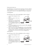
integrated LED/Valet® switch Things to remember when positioning the integrated LED/Valet® switch: • It should be visible from both sides and the rear of the vehicle, if possible. • It needs at least 1-1/2" clearance to the rear. • It is easiest to use a small removable panel, such as a switch blank or a dash bezel. Remove it before drilling your 5/16" hole. IMPORTANT! Do NOT use a step drill bit (unibit) for drilling the 5/16” hole. It is recommended to use a 5/16” drill bit.
IMPORTANT! Do not remove the fuse holder on the red (H1/11) wire. It ensures that the control module has it’s own fuse, of the proper value, regardless of how many accessories are added to the main power feed. finding the 12V switched ignition wire The ignition wire is powered when the key is in the run or start position. This is because the ignition wire powers the ignition system (spark plugs, coil) as well as the fuel delivery system (fuel pump, fuel injection computer).
finding a parking light wire The parking light wire is often found near the switch. Many cars have the switch built into the turn signal lever, and in these cars the parking light wire can be found in the steering column. The same wire is often available in the kick panel or running board. (+) parking light wire Use the following procedure to find (+) parking light wire with your multimeter. 1. Set to DCV or DC voltage (12V or 20V is fine). 2. Attach the (-) probe of the meter to chassis ground. 3.
4. Turn on the parking lights. If your meter shows (+)12V, turn off the parking lights and make sure it goes back to zero. 5. If it does return to zero, turn the parking lights back on and, using the dash light dimmer control, turn the brightness of the dash lights up and down. If the meter changes more than a volt when using the dimmer, look for another wire. If it stays relatively close to (+)12V, you have found your parking light wire.
main harness wire connection guide main harness wiring diagram H1/1 ___ ORANGE H1/2 ___ WHITE H1/3 ___ WHITE/BLUE H1/4 ___ BLACK/WHITE H1/5 ___ GREEN H1/6 ___ BLUE H1/7 ___ VIOLET H1/8 ___ BLACK H1/9 ___ YELLOW (+) Ignition Input H1/10 ___ BROWN (+) Siren Output H1/11 ___ RED H1/12 ___ RED/WHITE (-) 200mA Auxiliary Channel/Delayed Accessory Output (-) 500mA Ground When Armed (+)/(-) Light Flash Output No Function (-) 200mA Domelight Supervision Output (-) Door Trigger Input (-) Ins
IMPORTANT! Never interrupt any wire other than the starter wire. H1/2 WHITE light flash output: As shipped, this wire should be connected to the (+) parking light wire. It will supply a (+) 10A output. If the light flash polarity fuse jumper inside the unit is moved to the opposite position (see Internal Jumpers), this wire supplies a (-) 10A output. This is suitable for driving (-)parking light wires.
H1/3 WHITE/BLUE no function. H1/4 BLACK/WHITE (-) 200 mA domelight-supervision output: Connect this wire to the optional domelight supervision relay. IMPORTANT! This output is only intended to drive a relay. It cannot be connected directly to the domelight circuit, as the output cannot support the current draw of one or more bulbs. H1/5 GREEN (-) door trigger input: Most vehicles use negative door trigger circuits. Connect the green wire to a wire which shows ground when any door is opened.
H1/6 BLUE (-) instant trigger: This input will respond to a negative input with an instant trigger. It is ideal for hood and trunk pins and will report on zone one. H1/7 VIOLET (+) door trigger input: This wire is used in vehicles that have a positive (+) switched dome light circuit . Connect the violet wire to a wire that shows (+)12V when any door is opened, and ground when the door is closed.
H1/10 BROWN (+) siren output: This output can be used if an optional siren is installed. Connect this to the RED wire of the siren. Connect the BLACK wire of the siren to (-) chassis ground, preferably at the same point as the control module’s BLACK ground wire. H1/11 RED (+)12V constant power input: Before connecting this wire, remove the supplied fuse. Connect to the battery positive terminal or the constant 12V supply to the ignition switch.
auxiliary harness wire connection guide auxiliary harness wiring diagram H2/1 ___ BROWN (-) Horn Honk Output H2/2 ___ GREEN Arm Input H2/3 ___ RED H2/4 ___ BLUE Disarm Input H2/5 ___ GRAY (+) Trunk Release/Sensor Shunt Input H2/6 ___ VIOLET/BLACK H2/7 ___ YELLOW/BLACK Disarm Defeat Input No Function Light Flash Monitor Input auxiliary harness wiring guide H2/1 BROWN (-) horn honk output: This wire supplies a 200 mA (-) output that can be used to honk the vehicle’s horn.
vehicles operate this way. If this is the case connect the RED wire to the passenger unlock motor wire. When testing this wire be sure that it shows 12V (+) ONLY when the unlock button on the factory transmitter is pressed the second time to unlock the passenger doors. If the factory keyless entry system unlocks all of the doors at the same time, it is recommended that the H2/7 YELLOW/BLACK wire be used for disarm defeat input.
BLUE wire then the alarm zones are bypassed (See Feature menu 1/8) and will remain bypassed until the ground input is removed. This means that when the trunk is open with the factory transmitter the only triggers that remain active while the trunk is open are the doors and ignition. 3-seconds after the trunk is closed the bypassed zones again become active. H2/6 VIOLET/BLACK no function.
external relays—driver’s door unlock This system is used in many four-door GM sedans. To test for this type of system, probe the unlock wire from the interior switch (black or white). Unlock the driver’s door, by itself, using the factory remote. If the switch wire shows (+) 12V, then use the following diagram: NOTE: It is often easy to access the passenger unlock wire going to the rear door motor on the driver’s side. 18 © 2005 directed electronics, inc.
no priority—driver’s door unlock This type of keyless entry system is common in import vehicles as well as many Jeep vehicles. When unlocking the doors with the transmitter all doors unlock at the same time. It is recommended to use H2/7 YELLOW/BLACK wire for Disarm Defeat instead of the H2/3 RED wire. This input wire monitors the factory system light flash output. Connect this wire to the light flash wire that flashes when the factory transmitter is used.
door lock harness wire connection guide These door lock outputs are for Passive arming control of the factory door locks. They can also be used to control the door locks with the ignition switch for vehicle that do not have this feature in the factory RKE system. H3/A ___ GREEN H3/B ___ H3/C ___ BLUE (-) Lock, (+) Unlock Output Not Used (-) Unlock, (+) Lock Output The control module can control 2 common power door lock types without any additional parts.
four-pin optional sensor harness RED wire The red wire supplies constant power to the optional sensor. BLACK wire The black wire supplies ground to the optional sensor. BLUE, GREEN wires The blue and green wires are multiplex inputs. They are both tied to the same zone. If an input of less than 0.8 seconds is supplied to either wire the Warn-Away® response will occur. An input longer than 0.8 seconds to either wire will initiate the triggered sequence and report zone 4.
to learn lock: NOTE: Make sure the doors, hood and trunk are closed so the factory RKE system operates as it would when the user is using it. 1. With all the doors, hood and trunk closed: Press and HOLD the integrated LED/Valet® switch. 2. Within 5-seconds: Turn the ignition On and then Off (leave for less than 2-seconds in the on position). 3. Within 5-seconds: Release the integrated LED/Valet® switch. 4. Within 5-seconds: Press and release the integrated LED/Valet® switch once. 5.
NOTE: If the Unlock learn was unsuccessful, the Unlock procedure can be repeated by using the LOCK learn procedure, except that at step 4 press and release the integrated LED/Valet® switch TWICE. (The LED will flash in groups of two flashes.) to exit the learn routine: Do one of the following: z Turn the ignition on. z No activity for longer than 15 seconds. z Press the integrated LED/Valet® switch too many times.
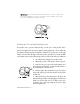
internal programming jumper A 10A fuse is used as both a fuse and a program jumper. This jumper determines the light flash output polarity. In the (+) position, the on-board relay is enabled and the unit will output (+)12V on the WHITE wire, H1/2. In the (-) position, the on-board relay is enabled for (-) output on the WHITE wire, H1/2. To access the jumper, remove the sliding door from on top of the control module, as shown below.
long term event history The control module will store the last 2 triggers in memory that are not erased when the ignition is turned on. This can be helpful for trouble shooting false alarm reports. To access the event history use the following procedure. 1. Turn the ignition switch off and press and hold the integrated LED/Valet® switch. 2. While holding the integrated LED/Valet® switch turn the ignition On. 3. Release the integrated LED/Valet® switch. 4.
feature programming The feature programming routine is used to access and change any of the feature settings in the two menus below. The feature settings can be accessed and changed by using one of the following: z The integrated LED/Valet® switch to enter the feature programming routine. z Use of the Directed Electronics Bitwriter® is recommended. Expanded programming options are only available when using the Directed Electronics Bitwriter®.
once a feature is programmed z Another feature(s) can be programmed. z The other feature menu can be selected. z The Learn Routine can be exited. accessing another feature z Release, then press and release the integrated LED/Valet® switch the number of times to advance from the feature just programmed to the next feature desired. z Press and hold the integrated LED/Valet® switch once more. z The horn will chirp to confirm the feature selected.
Bitwriter® ONLY features Due to memory limitations for this system, the following features can only be programmed using Directed’s Bitwriter® programmer. Factory default settings are shown in bold.
features #1 menu Factory default settings are shown in bold.
features #2 menu Factory default settings are shown in bold. NOTE: Feature step number 6 and 7 are not applicable to the this model. Feature Lock Button (one chirp) Step 30 Unlock Button (two chirps) 1 Ignition-Controlled Locking ON Ignition-Controlled Locking OFF 2 Ignition-Controlled UnLocking ON Ignition-Controlled Unlocking OFF 3 Active Locking 4 Door Lock Pulse Duration–0.8 sec. Door Lock Pulse Duration–3.5 sec.
master dealer remotes A master dealer remote can be programmed into the system for demonstration purposes. Generally, each salesman would carry a remote that would operate all the cars on the lot equipped with this system. The dealer remotes are binary transmitters that are detuned slightly in order to limit transmitting range. The dealer remote can be taught to the system by the following Transmitter Learn Routine.
5. Release. Once the transmitter is learned, the integrated LED/Valet® switch can be released. Channel Number Function Wire Color 1 Auto learn standard configuration N/A 2-8 No Function for Dealer Master Remote N/A 9 Delete all transmitters N/A When installing the system, it is possible to preset all of the operation settings using the master dealer remote. However, when the system is operated using the master dealer remote, a special set of dealer default settings are followed.
troubleshooting starter kill does not work: z Is the correct starter wire being interrupted? If the car starts when the starter kill relay is completely disconnected, the wrong starter wire has been cut and interrupted. • Is the yellow wire connected to “true” ignition? Make sure this wire is connected to a wire that has power in the run and start positions. the Valet® switch does not work. • Is it plugged into the correct socket? See the integrated LED/Valet® Switch section.
I can get into programming and change the feature settings, but when I use the remote the settings seem to change. • Are you using a binary, master dealer remote? Remember, you can program the settings using a master dealer remote. However, the unit will follow the dealer default settings when using a binary remote to operate the system. Door Lock Learn Routine does not learn door locks. • Check connections to be sure everything is properly connected.
Feature Programming routine does not work, the unit enters the learn routine then chirps and exits. • Check the Door Input connections. If the dome light is used for door trigger input, then the dome light must turn off in step 3. © 2005 directed electronics, inc.
36 © 2005 directed electronics, inc.
Integrated LED/Valet® Switch © 2005 directed electronics, inc.