
Installation Manual

Title: Installation Specifications and User Manual, Radar
Sensors
Doc. No. E567781
INSTALLATION SPECIFICATION Rev. 001, Page 8 of 14
5.0 SPECIFICATIONS
5.3 Installation Specifications For Individual Sensors
(cont’d)
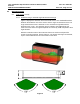
5.3.3 Effect Of Type- And Thickness Of Fascia Material
Autoliv has examined various fascia material samples with a thickness
of 2.5 – 4 mm. For those samples the radar signal is attenuated by
0.5 – 2 dB (corresponds to reduction of the range of coverage of
2 – 11%). The impact reducing material (foam) causes additional
attenuation, especially when water is absorbed. Therefore there shall
be no impact reducing material in the antenna areas as described in
5.2.2 – 5.2.3. There shall also be no metallic parts, snap-on contacts,
clips or double wall laminations in the antenna areas as described in
5.2.2 – 5.2.3.
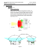
Fascia loss effects can be optimized by proper control of the material
thickness and dielectric constant. For example, a fascia material
measured to have a 2.2 dielectric constant would have less than 1 dB of
loss at a thickness of 4.5 mm. Autoliv can analyze sample materials to
determine the dielectric constant and proper thickness for optimal
performance. Thickness and dielectric constant must be controlled to a
tolerance of ±10% max to ensure optimal performance.
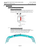
5.3.4 Effect of the paint
Depending upon the type of paint, number of coatings, base coats
used, etc. the attenuation of the radar signal was measured between
2 and 5 dB (corresponds to reduction of coverage between 11 and
25%). Because attenuation has significant impact on performance,
prior inspection of the material and paint samples are suggested.
Autoliv can characterize painted fascia samples to determine the radar
signal loss effects. Autoliv sensor specifications assume a maximum
signal loss (2-way) of 4 dB due to fascia effects. Materials and paints
that exhibit greater than 4 dB loss will degrade the specified
performance. As noted in 5.3.3 performance can be optimized by
proper control of the fascia material thickness and dielectric constant.
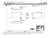
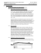
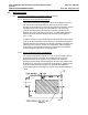
5.3.5 Smoothness of Fascia in Front of Antenna
Avoid sharp vertical or near vertical character lines in front of sensor
antenna. Horizontal character lines seem to have little effect on sensor
performance.