
Installation Manual

Title: Installation Specifications and User Manual, Radar
Sensors
Doc. No. E567781
INSTALLATION SPECIFICATION Rev. 001, Page 14 of 14
7.0 APPENDIX
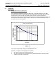
7.1. Range Performance vs Attenuation
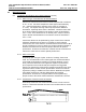
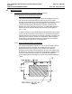
The chart below illustrates the effect of attenuation of the radar signals on the radar
sensor detection range. Factors that can cause attenuation of the radar signals include
fascia material, paint, dirt and mud buildup, foam material, or other mechanical
obstructions in the sensor field of view. For example, if a material is placed in front of the
sensor which attenuates the signal 12 dB (2 way loss) the maximum detection range of
the sensor will decrease by 50%.
Range vs Attenuation
0,00
0,10
0,20
0,30
0,40
0,50
0,60
0,70
0,80
0,90
1,00
0,00 5,00 10,00 15,00 20,00
Loss in dB
Figure 11
This device complies with Industry Canada RSS210 rules.
Operation is subject to the following two conditions:
1. This device may not cause interference and
2. This device must accept any interference, including interference that may cause
undesired operation of the device.