
Installation Manual

Title: Installation Specifications and User Manual, Radar
Sensors
Doc. No. E567781
INSTALLATION SPECIFICATION Rev. 001, Page 13 of 14
6.0 SLR SENSOR SYSTEM
6.3. Installation Dimensions
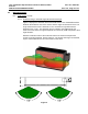
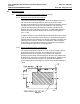
6.3.1 Y-direction
The Y location of the sensors will determine the extent of the coverage
zone and the size of any detection gaps. The location selections are
highly dependent on the desired application and bumper dimensions. In
general, for a 2 sensor longitudinal system sensors 2 &3 should be
located midway between the center of the bumper and the outer corner.
Bumper features (license plates etc.) may not allow this while
maintaining the guidelines of section 5. In this case the locations should
be as close to the ideal locations as possible while meeting the
requirements of section 5. A measurement check is required to verify
the actual installation implementation.
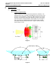
6.3.2 X-direction
The X location of the sensors not as critical as Y in terms of system
performance. In general the X locations will be dictated by the contour
of the bumper and the installation guidelines of section 5.
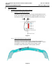
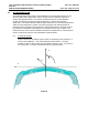
6.3.3 Azimuth angle
For best longitudinal coverage from sensors 2 & 3 the Azimuth angle of
the sensors has to be in the range of 0°. For systems, which are used
exclusively for parking distance control, larger angles up to 10°
might be
sensible if required to improve range of coverage.
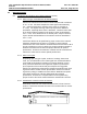
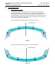
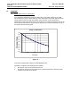
6.3.4 Elevation Angle
For best range performance the elevation angle of the sensors shall be
0 deg min, +1° max with respect to the ground (sensor radome surface
perpendicular (90°) to the ground). The main beam of the sensor (90°
to the installation position) may under no circumstances cross the plane
of the roadway before the desired coverage range.
For applications that only require short ranges (up to 5m) detection of
low objects (curbstones, low walls, etc.) may be desired. An incline
toward the ground of up to 10° can be used.