
User's Manual

Product Description, User Manual, Installation Guideline Doc. No. xxxxxxxxx
SENSOR MODULE, RADAR, SRR, NB Page 9 of 16
6.0 INTEGRATION AND MOUNTING GUIDELINES
This chapter describes the characteristics relevant to the installation of NB-SRR sensors in the bumper.
In addition general specifications are mentioned, which have to be followed for each position to enable
sufficient sensor performance. Therefore the following guidelines are to be observed carefully.
6.1.
Attachment to the vehicle
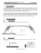
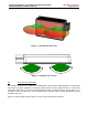
The sensor slides in a plastic bracket. The bracket is attached either to the vehicle chassis structure or
directly to the plastic fascia of the vehicle. The connector must face towards the rear of the vehicle to
ensure the performance characteristics listed in Table 1.
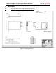
Figure 6 : Bracket Retention Features
6.2.
Detection Range / Azimuth Angle Measurement Range
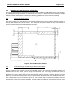
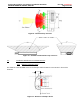
Figure 8 displays the detection area of the NB-SRR sensor. One should differentiate between the
detection area of the sensor and the angle measurement area. The angle measurement area is
reduced to ±50° around bore sight whereas the detection area is as wide as ±65° in azimuth. Within the
detection area of the antennas there must not be metal parts like screws, mounting brackets, license
plate etc. The impact reducing foam material, clips or fascia laminations has to be avoided in that area.
The azimuth keep out zone is shown in Figure 9. If the azimuth keep out zone is not followed, then the
performance of the sensor will be degraded. Consult Autoliv for guidance if the azimuth keep out zone
is violated.