
User's Manual

Product Description, User Manual, Installation Guideline Doc. No. xxxxxxxxx
SENSOR MODULE, RADAR, SRR, NB Page 2 of 16
TABLE OF CONTENTS
1.0 PRODUCT OVERVIEW 4
2.0 MOUNTING ORIENTATION 4
2.1. Vehicle Orientation 4
2.2. Sensor Orientation 4
3.0 SPECIFICATION 5
3.1. Sensor characteristics 5
4.0 BLOCK DIAGRAM 6
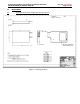
5.0 MECHANICAL 7
5.1. Envelope dimensions, weight and connector pin-out 7
5.2. Security protection – Tamper proof features 8
5.3. Label 8
6.0 INTEGRATION AND MOUNTING GUIDELINES 9
6.1. Attachment to the vehicle 9
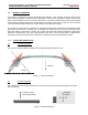
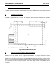
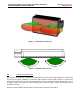
6.2. Detection Range / Azimuth Angle Measurement Range 9
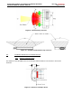
6.3. Detection Angle Elevation 10
6.4. Installation Guidelines For Individual Sensors 11
6.4.1 Distance to bumper fascia 11
6.4.2 Effect Of Type- And Thickness Of Fascia Material 12
6.4.3 Effect of the paint 12
6.4.4 Smoothness of Fascia in Front of Antenna 12
6.5. Feature installation guidelines 13
6.5.1 Sensor Connector Orientation 13
6.5.2 Vehicle Coordinate System 13
6.5.3 Identifying the Sensor Position 13
6.5.4 Y-direction recommendation 14
6.5.5 X-direction recommendation 14
6.5.1 Sensor Azimuth Angle (X-Y Plane) 14
6.5.2 Elevation Angle recommendation 14
6.5.1 Sensor Height and Elevation Angle Settings 15
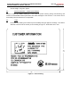
7.0 User information and Conformity to regulation 15
7.1. Required notice to the user in the USA for Part 15 Devices per FCC 15
7.2. Required notice to user in Canada per RSS-gen issue 3 15
7.3. Required notices to user in Japan 16