
User's Manual


Product Description, User Manual, Installation Guideline Doc. No. xxxxxxxxx
SENSOR MODULE, RADAR, SRR, NB Page 14 of 16
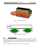
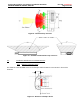
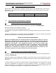
Figure 14 : Sensor position
6.5.4
Y-direction recommendation
The Y location of the sensors will determine the extent of the rear side Blind zone coverage. The
location selections are highly dependent on the desired application and bumper dimensions. Bumper
features (chrome trim, badges, etc.) may not allow this while maintaining the guidelines of section 5. In
this case the locations should be as close to the ideal locations as possible while meeting the
requirements of section 5. A measurement check is required to verify the actual installation
implementation.
6.5.5
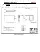
X-direction recommendation
In general, the X locations will be dictated by the contour of the bumper and the installation guidelines
of section 5. However, each sensor should be located as far rearward as possible while maintaining
other packaging requirements (radome to fascia B-side, angle, etc.).
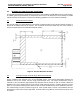
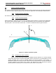
6.5.1
Sensor Azimuth Angle (X-Y Plane)
Each sensor shall be angled 50° +/-1deg rearward.
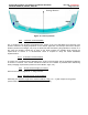
6.5.2
Elevation Angle recommendation
Preferably, the elevation angle of the sensors shall be 0 deg
[+1° / -1°] with respect to the ground
(sensor white cover surface perpendicular (90°) to the ground).
Right
Left
Driving direction