
User's Manual


Product Description, User Manual, Installation Guideline Doc. No. xxxxxxxxx
SENSOR MODULE, RADAR, SRR, NB Page 13 of 16
6.5.
Feature installation guidelines
The sensors should be located in the optimal location for best overall coverage and range performance.
The optimal locations will be dependent upon the specific application and the bumper characteristics.
6.5.1
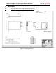
Sensor Connector Orientation
The Sensor connector orientation must be oriented rearward.
6.5.2
Vehicle Coordinate System
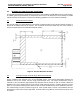
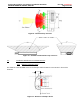
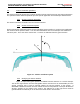
Figure 8 shows the coordinate system used for identifying sensor position in a multi-sensor application.
The arrows indicate positive values. The most forward location on the front bumper was selected as
reference point. The Z-axis is the vertical axis. Z-values are indicated from the ground surface.
Figure 13 : Vehicle coordinate system
6.5.3
Identifying the Sensor Position
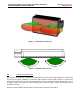
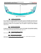
Figure 16 represents typical positions for REAR mounted Sensors on a vehicle bumper.
The left and right sensors are inter-changeable and the sensors have an addressable pin in the
vehicle connector that is used to logically identify the sensors position to the system. A
GROUND or OPEN connection from the vehicle harness to this particular contact pin dictates the
Sensor’s position on the vehicle to the system. The address pin of the right sensor must be
grounded while the address pin of the left sensor must remain unconnected.
Y
Z
ϕ
X