REVISION HISTORY © Rev AUTOLIV INC. THIS DOCUMENT AND THE DATA DISCLOSED HEREIN OR HEREWITH IS FOR THE PURPOSE OF CERTIFICATION DOCUMENTATION. 000 001 002 Description Date Initial Release Revised Certification Documentation Apprv’d 8/31/2011 3/15/2013 Autoliv Electronics Lowell. 1011B Pawtucket Blvd.
Product Description, User Manual, Installation Guideline SENSOR MODULE, RADAR, SRR, NB Doc. No. xxxxxxxxx Page 2 of 16 TABLE OF CONTENTS 1.0 PRODUCT OVERVIEW 4 2.0 MOUNTING ORIENTATION 2.1. Vehicle Orientation 2.2. Sensor Orientation 4 4 4 3.0 SPECIFICATION 3.1. Sensor characteristics 5 5 4.0 BLOCK DIAGRAM 6 5.0 MECHANICAL 5.1. Envelope dimensions, weight and connector pin-out 5.2. Security protection – Tamper proof features 5.3. Label 7 7 8 8 6.0 INTEGRATION AND MOUNTING GUIDELINES 6.1.
Product Description, User Manual, Installation Guideline SENSOR MODULE, RADAR, SRR, NB LIST OF FIGURES Figure 1.
Product Description, User Manual, Installation Guideline SENSOR MODULE, RADAR, SRR, NB 1.0 Doc. No. xxxxxxxxx Page 4 of 16 PRODUCT OVERVIEW This system is designed to provide the Blind Spot Detection, Lane Change Assist and Rear Cross Traffic warning features as defined by the ISO17387. It relies on two standalone 24GHz narrow band radar sensors located in the rear corners of the vehicle.
Product Description, User Manual, Installation Guideline SENSOR MODULE, RADAR, SRR, NB 3.0 3.1. Doc. No.
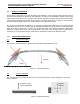
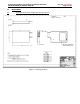
Product Description, User Manual, Installation Guideline SENSOR MODULE, RADAR, SRR, NB 5.0 5.1. MECHANICAL Envelope dimensions, weight and connector pin-out Figure 4 : Envelope Drawing Doc. No.
Product Description, User Manual, Installation Guideline SENSOR MODULE, RADAR, SRR, NB Doc. No. xxxxxxxxx Page 8 of 16 Sensor Weight: 90 grams approx. 5.2. Security protection – Tamper proof features Sensor is sealed by LASER Welding the cover with the plastic housing during manufacturing and cannot be disassembled without permanent and visible damages to the structure. The sensor has no serviceable parts and therefore is not repairable. 5.3.
Product Description, User Manual, Installation Guideline SENSOR MODULE, RADAR, SRR, NB 6.0 Doc. No. xxxxxxxxx Page 9 of 16 INTEGRATION AND MOUNTING GUIDELINES This chapter describes the characteristics relevant to the installation of NB-SRR sensors in the bumper. In addition general specifications are mentioned, which have to be followed for each position to enable sufficient sensor performance. Therefore the following guidelines are to be observed carefully. 6.1.
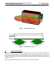
Product Description, User Manual, Installation Guideline SENSOR MODULE, RADAR, SRR, NB Doc. No. xxxxxxxxx Page 10 of 16 Figure 7 : Azimuth Detection zone Figure 8 : Azimuth keep out zone 6.3. Detection Angle Elevation The detection angle of ±10° is related to the 3dB points of the elevation transmit pattern; this means the area where the signal amplitude is reduced by 3dB compared to bore sight direction.
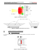
Product Description, User Manual, Installation Guideline SENSOR MODULE, RADAR, SRR, NB Doc. No. xxxxxxxxx Page 11 of 16 Figure 9 : Elevation keep out zone Figure 10 : Azimuth and Elevation Keep out zones 6.4. Installation Guidelines For Individual Sensors 6.4.1 Distance to bumper fascia The distance of the NB-SRR sensor to the bumper shall be between 5 and 20 mm in front of the antennas.
Product Description, User Manual, Installation Guideline SENSOR MODULE, RADAR, SRR, NB 6.4.2 Doc. No. xxxxxxxxx Page 12 of 16 Effect Of Type- And Thickness Of Fascia Material Autoliv has examined various fascia material samples with a thickness of 2.5 – 4 mm. For those samples, the radar signal is attenuated by 0.5 – 2 dB (corresponds to reduction of the range of coverage of 2 – 11%). Impact reducing material (foam) causes additional attenuation, especially when water is absorbed.
Product Description, User Manual, Installation Guideline SENSOR MODULE, RADAR, SRR, NB 6.5. Doc. No. xxxxxxxxx Page 13 of 16 Feature installation guidelines The sensors should be located in the optimal location for best overall coverage and range performance. The optimal locations will be dependent upon the specific application and the bumper characteristics. 6.5.1 Sensor Connector Orientation The Sensor connector orientation must be oriented rearward. 6.5.
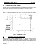
Product Description, User Manual, Installation Guideline SENSOR MODULE, RADAR, SRR, NB Doc. No. xxxxxxxxx Page 14 of 16 Driving direction Left Right Figure 14 : Sensor position 6.5.4 Y-direction recommendation The Y location of the sensors will determine the extent of the rear side Blind zone coverage. The location selections are highly dependent on the desired application and bumper dimensions. Bumper features (chrome trim, badges, etc.
Product Description, User Manual, Installation Guideline SENSOR MODULE, RADAR, SRR, NB 6.5.1 Doc. No. xxxxxxxxx Page 15 of 16 Sensor Height and Elevation Angle Settings Please follow the following table for setting the elevation angle of the Side Blind Spot / Lane change Assist sensor. The sensor shall not be placed below 500mm or above 600mm without review and approval by Autoliv. Sensor Height from Ground 550 – 650 mm 7.0 7.1.
Product Description, User Manual, Installation Guideline SENSOR MODULE, RADAR, SRR, NB 7.3. Doc. No. xxxxxxxxx Page 16 of 16 Required notices to user in Japan This device has been granted a designation number by the Ministry of Internal Affairs and Communications according to the Ordinance concerning the Technical Regulations Conformity Certification etc.