
Installation Instructions

Title:
Installation Specifications and User Manual, Radar
Sensor, 24 GHz
Doc. No. E E814702
INSTALLATION SPECIFICATION Rev. 000, Page 6 of 16
5.0 SPECIFICATIONS
5.2 24 GHz Sensor (cont’d)
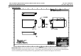
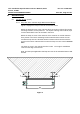
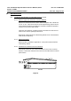
5.2.3 Conductive material keep-out zone, Angle Elevation
Figure 3
the conductive material keep out area of the 24 GHz Sensor
Within the keep out zone there must not be metal parts like screws, mounting
brackets, license plate etc. The impact reducing foam material, clips or fascia
laminations has to be avoided in that area.
This conductive material keep out zone in elevation is ±30°. This angle is
established 7mm from the edge of the sensor.
Figure 3
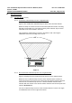
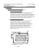
5.2.4 Non-Conductive material keep-out zone, Angle Elevation
Figure 3a displays the Non-Conductive keep out area of the 24GHz Sensor.
Within the non-conductive keep out zone of the antennas there must be no
vertical character lines present in the fascia. Mounting bracket material shall not
enter the non-conductive keep out zone. Bracket retention features which
interface with the surface of the sensor radome shall not enter the keep out zone
noted in
Section 5.2.5
The non-conductive keep out zone in the elevation direction is ±20°. This angle
is established 7mm from the edge of the sensor.