
Installation Instructions

Title:
Installation Specifications and User Manual, Radar
Sensor, 24 GHz
Doc. No. E E814702
INSTALLATION SPECIFICATION Rev. 000, Page 15 of 16
6.0 24 GHZ SENSOR SYSTEM
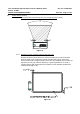
6.3. Installation Dimensions
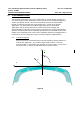
6.3.1 Y-Direction
The Y location of the sensors will determine the extent of the coverage
zone and the size of any detection gaps. The location selections are
highly dependent on the desired application and bumper dimensions. In
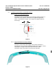
general, for a 2 sensor longitudinal system sensors 2 &3 should be
located midway between the center of the bumper and the outer corner.
Bumper features (license plates etc.) may not allow this while
maintaining the guidelines of section 5. In this case the locations should
be as close to the ideal locations as possible while meeting the
requirements of section 5. A measurement check is required to verify
the actual installation implementation.
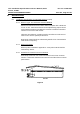
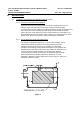
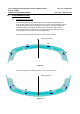
6.3.2 X-Direction
The X location of the sensors not as critical as Y in terms of system
performance. In general the X locations will be dictated by the contour
of the bumper and the installation guidelines of section 5.