
Installation Instructions

Title:
Installation Specifications and User Manual, Radar
Sensor, 24 GHz
Doc. No. E E814702
INSTALLATION SPECIFICATION Rev. 000, Page 14 of 16
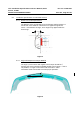
6.0 24 GHZ SENSOR SYSTEM
6.2. Numbering of the Sensors
The following provides a guideline for sensor numbering (addressing) in a
multi-sensor system. The example used is for a front and rear bumper system.
Each bumper contains up to 4 sensors connected on a private CAN bus. A
separate CAN bus is used for the front and rear bumpers. The sensors
transmit data over the CAN bus to a centralized processor which performs
sensor data fusion and runs the desired application.
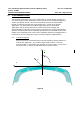
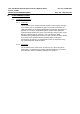
Figure 9 shows the numbering used for a front sensor system.
Figure 9
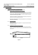
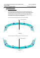
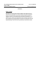
Figure 10 shows the numbering used for a rear sensor system.
Figure 10
1F
2F
3F
4F
Driving direction
1R
2R
3R
4R
Driving direction