
Installation Instructions

Title:
Installation Specifications and User Manual, Radar
Sensor, 24 GHz
Doc. No. E E814702
INSTALLATION SPECIFICATION Rev. 000, Page 12 of 16
5.0 SPECIFICATIONS
5.3 Installation Specifications for Individual Sensors (cont’d)
5.3.9 ESS-SRR Application
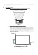
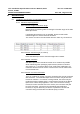
5.3.9.1 Sensor Height and Elevation Angle
Please follow the following table for setting the elevation angle of the
ESS-SRR sensor.
If packaging above 500 mm is not possible, please consult Autoliv
resident engineer to assess alternate locations.
The sensor can not be mounted below 400 mm under any circumstance,
and 500 mm is strongly recommended for vehicle rear applications.
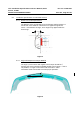
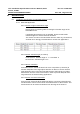
5.3.9.2 Sensor Azimuth Angle (X-Y Plane)
Front Sensors: Azimuth Angle 4° - 7° ± 1° outboar d
Rear Sensor: Azimuth Angle 0° ± 1°
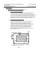
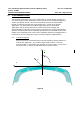
5.3.9.3 Sensor Y-Position
Front SSR sensors shall be located in the cross car position (Y direction) to
maintain adequate close range object detection at 400 mm. The 40° azimuth
angle detection cones of the two front SRR sensors shall intersect no farther
than 400 mm from the center of the fascia in order to provide adequate short
range detection for forward looking applications.
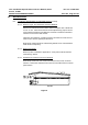
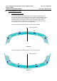
5.3.9.4 Sensor Connector Orientation
Front and rear sensors shall be positioned with the connector pointed inboard
and the distance from the fascia shall not fall below 5mm or above 20mm. This
measurement can be measured 8-10mm from the edge of the antenna.