
Installation Instructions

Title:
Installation Specifications and User Manual, Radar
Sensor, 24 GHz
Doc. No. E E814702
INSTALLATION SPECIFICATION Rev. 000, Page 11 of 16
5.0 SPECIFICATIONS
5.3 Installation Specifications for Individual Sensors (cont’d)
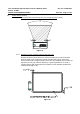
5.3.8 Side Blind Spot Application
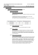
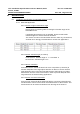
5.3.8.1 Sensor Height vs. Elevation Angle
Please follow the following table for setting the elevation angle of the Side
Blind Spot sensor.
If packaging above 500 mm is not possible, please consult Autoliv
resident engineer to assess alternate locations.
The sensor can not be mounted below 400 mm under any circumstance.
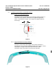
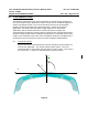
5.3.8.2 Sensor Azimuth Angle (X-Y Plane)
Each Side Blind Spot sensor should be angled 20° re arward.
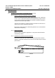
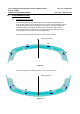
5.3.8.3 Sensor X-Position
Side Blind Spot sensor should be located as far rearward as possible
while maintaining other packaging requirements (radome to fascia B-
side, angle, etc.). For RCTA (Rear Cross Traffic Alert) application, the
maximum distance from the center of sensor to the rear of vehicle shall
not exceed 300 mm.
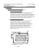
5.3.8.4 Sensor Connector Orientation
There is a tradeoff on sensor connector orientation that must be reviewed
with Customer. The Side Blind Spot sensor connector may be oriented
forward or rearward. If connector is facing forward, the sensor may be
positioned further rearward which is a performance benefit for the RCTA
(Rear Cross Traffic Alert) application. Also, if the connector is facing
forward, the more sensitive side of the sensor (non-connector side) will
be facing rearward - a benefit for the Side Blind Spot application.
However, it may be advised by Customer to position the sensor with
connector facing rearward due to water/salt spray concerns.