Trademarks Autel®, MaxiSys®, MaxiDAS®, MaxiScan®, MaxiCheck®, MaxiRecorder®, and MaxiCheck® are trademarks of Autel Intelligent Technology Corp., Ltd., registered in China, the United States and other countries. All other marks are trademarks or registered trademarks of their respective holders.
Safety Information For your own safety and the safety of others, and to prevent damage to the device and vehicles upon which it is used, it is important that the safety instructions presented throughout this manual be read and understood by all persons operating or coming into contact with the device. There are various procedures, techniques, tools, and parts for servicing vehicles, as well as in the skill of the person doing the work.
Safety Instructions The safety messages herein cover situations Autel is aware of. Autel cannot know, evaluate or advise you as to all of the possible hazards. You must be certain that any condition or service procedure encountered does not jeopardize your personal safety. DANGER When an engine is operating, keep the service area WELL VENTILATED or attach a building exhaust removal system to the engine exhaust system.
Refer to the service manual for the vehicle being serviced and adhere to all diagnostic procedures and precautions. Failure to do so may result in personal injury or damage to the test equipment. To avoid damaging the test equipment or generating false data, make sure the vehicle battery is fully charged and the connection to the vehicle DLC is clean and secure. Do not place the test equipment on the distributor of the vehicle. Strong electro-magnetic interference can damage the equipment.
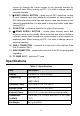
CONTENTS 1 USING THIS MANUAL......................................................................................1 CONVENTIONS..................................................................................................... 1 2 USING THE SCAN TOOL................................................................................3 TOOL DESCRIPTION............................................................................................ 3 SPECIFICATIONS.....................................................
VIEWING VEHICLE INFORMATION..................................................................... 37 MODULES PRESENT..........................................................................................38 DTC LOOKUP....................................................................................................39 5 DTC LOOKUP..................................................................................................40 6 PLAYBACK DATA...............................................................
1 Using This Manual This manual contains device usage instructions. Some illustrations shown in this manual may contain modules and optional equipment that are not included in your system. Contact your sales representative for availability of other modules and optional tools or accessories. Conventions The following conventions are used. Bold Text Bold text is used to highlight selectable items such as buttons and menu options. Tap OK.
IMPORTANT Keep the cable away from heat, oil, sharp edges and moving parts. Replace damaged cables immediately. Hyperlink Hyperlinks, or links, that take you to other related articles, procedures, and illustrations are available in electronic documents. Blue italic text indicates a selectable hyperlink and blue underlined text indicates a website link or an email address link. Illustrations Illustrations used in this manual are samples, the actual testing screen may vary by test vehicle.
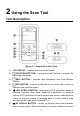
2 Using the Scan Tool Tool Description Figure 2- 1 Sample Scan Tool View 1) LCD DISPLAY – displays menus and test results. 2) FUNCTION BUTTONS – corresponds with “buttons” on screen for executing commands. 3) HELP BUTTON – provides help information and Code Breaker function. 4) ESC BUTTON – cancels a selection (or an action) from a menu or returns to the previous screen.
moves up through the current screen to the previous screens for additional data. When looking up DTC, it is used to change value of selected character. 7) RIGHT SCROLL BUTTON – when look up DTC definitions, moves to next character and view additional information on next screens if DTC definition covers more than one screen; views next screen or next frames of recorded data. It is also used to view next trouble code when viewing DTCs. 8) OK BUTTON – confirms a selection (or action) from a menu.
Accessories Included 1) OBDII Cable – provides power to tool and communicates between tool and vehicle. 2) USB Cable – used to upgrade the scan tool and to print retrieved data. 3) TF Card – used to store data. 4) User Manual – instructions on tool operations. 5) Quick Guide – instructions on device connection and tool registration and update. Keypad No solvents such as alcohol are allowed to clean the keypad or display. Use a mild nonabrasive detergent and a soft cotton cloth.
Figure 2- 2 Sample Main Screen Vehicle Coverage The AutoLink AL629 OBDII/EOBD Scanner is specially designed to work with all OBD II compliant vehicles, including those equipped with next-generation protocol -- Control Area Network (CAN). It is required by EPA that all 1996 and newer vehicles (cars and light trucks) sold in the United States must be OBD II compliant and this includes all Domestic, Asian and European vehicles.
Toyota, Vauxhall, Volvo, Volkswagen, Renault, Peugeot, Lancia, Fiat, Dacia, Citroen, Alfa, Abarth. More vehicle supports will come out with new updates released. Product Troubleshooting This part describes problems that you may encounter while using the scan tool. Vehicle Linking Error A communication error occurs if the scan tool fails to communicate with the vehicle’s ECU (Engine Control Unit). You need to do the following to check up: Verify that the ignition is ON.
necessary. Check vehicle battery to make sure it is still good with at least 8.0 volts. NOTE Avoid electrostatic interference during operation. If a failure occurs due to electrostatic interference, please try to operate again.
3 Scan The AutoLink AL629 is a powerful OBDII scan tool that provide basic diagnosis and read and erase codes for four systems: ABS, SRS, engine, and transmission. Before using this scan function, please follow the on-screen instructions for selections from vehicle manufacturer to model year to identify the vehicle being tested. 1. Turn the ignition on but do not start the engine. 2. Locate the 16-pin OBDII diagnostic connector (usually under the dash near the steering column).
Figure 3- 2 Sample Vehicle Manufacture Screen Use the UP/DOWN scroll button to select the correct Vehicle Model, Year, and Type step-by-step. The steps may vary by test vehicles. After all the selections are made, a vehicle information summary will pop up for your confirmation, press Yes to continue. The four systems will pop up for you to choose, the name of the system may vary by test vehicles.
Read Codes 1. Select ABS from the system list. The list may vary by test vehicles. Figure 3- 3 Sample System List 2. Select Read codes from the diagnostic function list. All the DTCs of the ABS control module are displayed. Press Save to save the data or press ESC to exit without saving. For some trouble codes, you may press OK button to view detailed information of the trouble codes.
Figure 3- 6 Sample ABS Trouble Codes Screen 2 Figure 3- 4 Sample Diagnostic Function Menu Erase Codes 1. Select Erase codes from the diagnostic function list (Figure 3- 4). 2. Follow the on-screen instruction and make sure the ignition on and engine off. Press Yes to continue.
3. A confirmation message “DTCs and freeze data will be deleted. Are you sure you want to continue?” will pop up to ask for your confirmation. Press Yes to continue. 4. Erase Codes command will be sent and you can perform Read Codes function to verify. Press any key to continue.
SRS The purpose of the SRS light on your instrument panel is to alert you of a potential problem with your supplemental restraint system. Use the AL629 to have the system checked if: The light does not come on when you turn the ignition ON. The light stays on after the engine starts. The light comes on or flashes while you are driving. Read Codes 1. Select SRS or Restraints control module from the system list. The list may vary by test vehicles (Figure 3- 3). 2.
4. Erase Codes command will be sent and you can perform Read Codes function to verify. Press any key to continue. Engine The “Malfunction Indicator Lamp” (or Check Engine Light) is supposed to come on when a problem occurs in the engine control system that affects emission. Depending on how the system is configured and the nature of the problem, the lamp may come on and go off, remain on continuously or flash.
3. A confirmation message “DTCs and freeze data will be deleted. Are you sure you want to continue?” will pop up to ask for your confirmation. Press Yes to continue. 4. Erase Codes command will be sent and you can perform Read Codes function to verify. Press any key to continue. Transmission Read Codes 1. Select Transmission control module from the system list. The list may vary by test vehicles (Figure 3- 3). 2. Select Read codes from the diagnostic function list (Figure 3- 4). 3.
4 OBDII Diagnostics The OBD II Diagnostics function is a fast-access option that allows you to carry out a quick test on the engine system of OBD II vehicles. When more than one vehicle control module is detected by the scan tool, you will be prompted to select the module where the data may be retrieved. The most often to be selected are the Powertrain Control Module [PCM] and Transmission Control Module [TCM]. CAUTION: Don’t connect or disconnect any test equipment with ignition on or engine running.
status) on screen. Press ESC button for Diagnostic Menu to come up. Figure 4- 1 Sample Diagnostic Menu If more than one module is detected, you will be prompted to select a module before testing. Use the UP/DOWN scroll button to select a module and press the OK button. System Status System Status shows the MIL Status, codes found, and monitors status.
the key on engine running (KOER). Stored Codes are also known as “hard codes”, which are fault codes, or trouble codes that have been stored in the vehicle computer memory because the faults have reoccurred for more than a specified amount of key-cycles. These codes will cause the control module to illuminate the malfunction indicator light (MIL) when emission-related fault occurs. Pending Codes are also referred to as “maturing codes” or “continuous monitor codes”.
If there is not any Diagnostic Trouble Code, the display indicates “No (pending) codes are stored in the module!” Wait a few seconds or press any key to return to previous screen. NOTE Permanent Codes function is available for merely vehicles supporting the CAN protocols. 3) View DTCs and their definitions on screen. 4) If more than one DTC is found, use the LEFT/RIGHT scroll button to check all the codes.
Figure 4- 4 Sample Erase Codes Screen 1 If you do not want to proceed with erasing codes, press ESC button or select NO to exit and return to previous screen. If you press Yes function key or OK button, a warning message will come up asking your confirmation. Figure 4- 5 Sample Erase Codes Screen 2 3) Press the OK button to confirm. If the codes are cleared successfully, an “Erase Done!” confirmation message shows on the display.
Figure 4- 6 Sample Erase Codes Screen 3 4) If the codes are not cleared, then an “Erase Failure. Turn Key on with Engine off!” message appears. Press any key to return to Diagnostic Menu. Live Data In this function, you can not only read the live data but also record data for later review. View Data The View Data function allows viewing of live or real time PID data of vehicle’s computer module(s).
Figure 4- 7 Sample Live Data Screen 2) View live PIDs on the screen. Use the UP/DOWN scroll button for more PIDs if additional information is available on more than one page. If the “Graphics” on the bottom appears when a PID is highlighted, graphic information is available. Select Graphics to view graph. PID name, current value, maximum and minimum values are displayed on the screen.
3) Select Text to return to text viewing of PID data. Select Save to record retrieved live data and PID graphs. Select Pause to suspend viewing. You could resume the viewing process again by selecting Start. Press the ESC button to return to previous menu. Viewing Custom List 1) To view customized PID data, use the UP/DOWN scroll button to select Custom List from Live Data menu and press the OK button (Figure 4-7).
Figure 4- 10 Sample Custom List Screen 2 4) Press Save to save the data or ESC to return to previous menu. Record Data The Record Data function allows recording vehicle modules’ Parameter Identification (PID) data to help diagnose intermittent vehicle problems. You could save data files to the SD card and then use the Playback function to view the saved files. NOTE The length of time for each frame varies per vehicle. Generally, one frame of data is about 1/4 second, or 4 frames per second.
Figure 4- 11 Sample Recording Data Screen 1 If you record live data under graph mode, following screen shows. Figure 4- 12 Sample Recording Data Screen 2 NOTE The scan tool can only playback text data even though the data is saved in graphic mode. 2) When there is not enough memory space, a warning message prompting to delete previously recorded data. Select OK to return to the previous menu. 3) Select Pause to suspend recording. You could resume the recording process again by selecting Start.
Freeze Frame Freeze Frame Data allows the technician to view the vehicle’s operating parameters at the moment a DTC (Diagnostic Trouble Code) is detected. For example, the parameters may include engine speed (RPM), engine coolant temperature (ECT), or vehicle speed sensor (VSS) etc. This information will aid the technician by allowing the parameters to be duplicated for diagnostic and repair purposes.
Retrieving I/M Readiness Status I/M Readiness function is used to check the operations of the Emission System on OBDII compliant vehicles. It is an excellent function to use prior to having a vehicle inspected for compliance to a state emissions program. CAUTION: By clearing trouble codes you also clear the readiness status for the individual emission system readiness tests. In order to reset these monitors, the vehicle must be driven through a complete drive cycle with no trouble codes in memory.
Figure 4- 14 Sample I/M Readiness Screen 4) Use the UP/DOWN scroll button, as necessary, to view the status of the MIL light (ON or OFF) and the following monitors: For spark ignition engines: MIS – Misfire Monitor FUEL – Fuel System Monitor CCM – Comprehensive Component Monitor EGR – EGR System Monitor O2S – O2 Sensors Monitor CAT – Catalyst Monitor EVAP – Evaporative System Monitor HTR – O2 Sensor Heater Monitor AIR – Secondary Air Monitor HCAT – Heated Catalyst Mo
EGS – Exhaust Gas Sensor Monitor PM – PM Filter Monitor Figure 4- 15 Sample since DTCs Cleared Screen 5) If the vehicle supports readiness test of “This Drive Cycle”, a screen of the following displays. 6) Use the UP/DOWN scroll button for more PIDs if additional information is available on more than one page. Or use the LEFT/RIGHT scroll button to view PIDs in the previous/next page. 7) Press the ESC button to return to Diagnostic Menu.
tests on the oxygen (O2) sensors to identify problems related to fuel efficiency and vehicle emissions. These tests are not on-demand tests and they are done automatically when engine operating conditions are within specified limits. These test results are saved in the on-board computer's memory. The O2 Monitor Test function allows retrieval and viewing of O2 sensor monitor test results for the most recently performed tests from the vehicle's on-board computer.
Figure 4- 18 Sample Nonsupport Screen 4) View test results of selected O2 sensor.
Figure 4- 20 Sample O2 Sensor Test Result 5) Use the UP/DOWN scroll button to view more screens of data if additional information is available in more than one page. 6) Press the ESC button to return to the previous menu. On-Board Monitor Test The On-Board Monitor Test is useful after servicing or after erasing a vehicle’s control module memory.
Figure 4- 21 Sample Vehicle Manufacturer Screen 4) After you select the vehicle manufacturer, the scan tool shows the On-Board Monitors tests for specific monitoring systems. 5) From On-Board Monitor Test menu, use the UP/DOWN scroll button to select a test to view and press the OK button. Figure 4- 22 Sample On-Board Monitor Test Menu If the vehicle under test does not support the mode, an advisory message will be displayed on the screen.
Figure 4- 23 Sample Nonsupport Screen For CAN-equipped vehicles, test results displayed can be as below: Figure 4- 24 Sample Test Data Screen 6) Press ESC button to return to the previous menu. Component Test The Component Test function allows initiating a leak test for the vehicle's EVAP system. The scan tool itself does not perform the leak test, but commands the vehicle's on-board computer to start the test.
1) Use the UP/DOWN scroll button to select Component Test from Diagnostic Menu and press the OK button (Figure 4- 1). 2) Wait for the scan tool to display the Component Test menu. Figure 4- 25 Sample Component Test Screen 1 Figure 4- 26 Sample Component Test Screen 2 3) If the test has been initiated by the vehicle, a confirmation message will be displayed on the screen. 4) Some vehicles do not allow scan tools to control vehicle systems or components.
Viewing Vehicle Information The Vehicle Info. function enables retrieval of Vehicle Identification No. (VIN), Calibration ID Nos. (CINs), Calibration Verification Nos. (CVNs) and In-use Performance Tracking on 2000 and newer vehicles that support Mode 9. 1) Use UP/DOWN scroll button to select Vehicle Info. from the Diagnostic Menu and press OK button (Figure 4- 1). 2) An advisory message comes up to remind you. Wait a few seconds or press any key to continue.
Figure 4- 28 Sample Vehicle ID Number Screen 6) Press the ESC button to return previous menu. Modules Present The Modules Present function allows viewing of the module IDs and communication protocols for OBD2 modules in the vehicle. 1) Use the UP/DOWN scroll button to select Modules Present from Diagnostic Menu and press OK button (Figure 4- 1). 2) View modules present with their IDs and communication protocols.
DTC Lookup Refer to DTC Lookup for detailed information.
5 DTC Lookup The DTC Lookup function allows user to search definitions of DTC stored in built-in DTC library. 1) Use the UP/DOWN scroll button to select DTC Lookup from Main Screen and press OK button (Figure 2- 2). 2) Select Show and a soft keyboard will pop up. Use LEFT/RIGHT button and UP/DOWN button to move to the desired character, then press OK button to confirm. 3) After you input the DTC code, select Finish and the scan tool will display this code’s definition on screen.
Figure 5- 2 Sample DTC Lookup Screen 3 4) Press Yes or OK button to proceed. The scan tool will display DTC definition as below. Figure 5- 3 Sample DTC Lookup Screen 4 5) Use the LEFT/RIGHT scroll button to view the previous / next DTC. Select Save to record code definition. For manufacturer specific codes, the AutoVIN function embedded in this tool will automatically display the definition of the code.
6 Playback Data The Playback Data function allows viewing data from last test recorded by the scan tool. Review Data 1) Use the LEFT/RIGHT scroll button to select Playback from Main Screen (Figure 2- 2), and press the OK button. Wait for the Review Data screen to appear. Figure 6- 1 Sample Review Data Screen 1 2) To review data saved in the scan function, select Scan in the Replay menu. To review data saved in the OBD II function, select OBD II in the Replay menu. Then press OK button to continue.
Figure 6- 2 Sample Review Data Screen 2 If no data from previously tested vehicle is recorded, a message “No data available!” shows on the screen. Review selected data on screen. Figure 6- 3 Sample Reviewing Data Screen 3 Delete Data By selecting Delete on the Scan or OBD II screen, you are allowed to erase the selected data on the scan tool. Review the recordings thoroughly before erasing. You could also erase all recordings by select Delete All.
Print Data By selecting Print option on the trouble codes screen, you are allowed to send the recorded files to your computer and then to the printer. For more details, please refer to Print Data.
7 System Setup The System Setup functions allow you to adjust default settings and view information about the scan tool. 1) Language: Selects the desired language. 2) Unit: Sets the unit of measure to English or Metric. 3) Beep: Turns on/off beep. 4) Key Test: Checks if the keyboard is working properly. 5) LCD Test: Checks if the LCD display is working properly. NOTE Settings of the unit will remain until change to the existing settings is made.
1) From System Setup screen, use the UP/DOWN scroll button and LEFT/RIGHT scroll button to select Language, and press the OK button. Figure 7- 2 Sample Language Set Screen 2) Use the UP/DOWN scroll button to select the desired language and press the OK button to save your selection and return to previous screen. Unit of Measure Metric is the default measurement unit. 1) From System Setup screen, use the LEFT/RIGHT scroll button to select EN/METRIC and press the OK button.
select the desired unit of measurement. 3) Press the OK button to save your selection and return to previous menu. Or, press the ESC button to exit without saving. Beep Set The default setting is Beep On. 1) From System Setup screen, use the UP/DOWN scroll button and LEFT/RIGHT scroll button to select Beep and press the OK button. 2) From Beep Set menu, use the LEFT/RIGHT scroll button to select ON or OFF to turn on/off the beep.
Figure 7- 5 Sample Key Test Screen 3) Double press ESC to return to previous menu. LCD Test The LCD Test function checks if the LCD display is working normally. 1) From System Setup screen, use the UP/DOWN scroll button and LEFT/RIGHT scroll button to select LCD Test, and press the OK button. 2) Look for missing spots in the red, green, blue, black and white LCD display. 3) When completed, press the ESC button to exit.
8 About The About function allows viewing of some important information such as serial number and software version number of the scanner. 1) From Main Screen (Figure 2- 2), use the UP/DOWN scroll button and LEFT/RIGHT scroll button to select About and press the OK button, wait for the About screen to appear. 2) View tool information on screen. Press the ESC button to exit.
9 Print and Update Print Data The Print Data function allows printing out DTC data recorded by the scan tool by connecting the scan tool to a PC or laptop with the USB cable supplied. 1) Download the Maxi PC Suite from www.autel.com and install. 2) Connect the scanner to computer with the USB cable supplied. 3) Run Autel Printer software on computer. 4) Select Playback function in Main Screen of the scan tool. In Scan/OBDII screen, use the UP/DOWN scroll button to select the data you want to print.
NOTEPAD window with all recorded data displayed. 7) Copy – Copy all data in the textbox to the clipboard. Clear – Delete all data in the textbox. Exit – Quit the operation. You are also allowed to edit, copy, and delete the data in the Printer window. NOTE The scan tool can only print text data even though the data is saved in graphic mode. The print function is not available on Mac for the present. Software Update This function allows you to update the scan tool software through a computer.
bottom. A product registration screen will display. 6. The device’s serial number and password is located in the About section of the Settings application on the tool 7. Select your product model, enter the product serial number and password on the Product Registration screen, and click Submit to complete the registration procedure. NOTE Please refer to section About for Product Serial No. and Register Password. Update Procedure Autel frequently releases software updates that you can download.
Password?] to link to our website and find your password back. 4. Select the product type and serial number, click OK to continue. 5. In the Update window, select the items you want to install. Usually, you should install all available updates. Figure 9- 3 Sample Update Window Generally, there are two ways to update programs: Batch Update 1. Select the programs that you would update by clicking on the check boxes next to those items. Then click the Update All button on the right bottom of the screen.
View or Delete Programs To view the list of installed programs or to delete an installed program, please follow these steps: 1. Click on the Installed tag entry and the page will show the list of programs installed. 2. Select the program(s) that you want to delete. 3. Batch delete: Select the programs that you want to delete by clicking on the check boxes to the left of those items. Then click the Uninstall All button on the right bottom of the screen.
10 Compliance Information FCC Compliance This device complies with Part 15 of the FCC rules and Industry Canada’s license-exempt RSSs. Operation is subject to the following two conditions: 1. This device may not cause harmful interference. 2. This device must accept any interference received, including interference that may cause undesired operation. Cet appareil est conforme aux CNR exempts de licence d’Industrie Canada. Son fonctionnement est soumis aux deux conditions suivantes: 1.
-- Increase the separation between the equipment and receiver. -- Connect the equipment into an outlet on a circuit different from that to which the receiver is connected. -- Consult the dealer or an experienced radio/TV technician for help. Changes or modifications not expressly approved by the party responsible for compliance could void the user’s authority to operate the equipment. SAR The radiated output power of this device is below the FCC radio frequency exposure limits.
11 Warranty and Service Limited One Year Warranty Autel warrants to its customers that this product will be free from all defects in materials and workmanship for a period of one (1) year from the date of the original purchase, subject to the following terms and conditions: 1) The sole responsibility of Autel under the Warranty is limited to either the repair or, at the option of Autel, replacement of the scan tool at no charge with Proof of Purchase. The sales receipt may be used for this purpose.