© 2008 Autodesk, Inc. All rights reserved. Except as otherwise permitted by Autodesk, Inc., this publication, or parts thereof, may not be reproduced in any form, by any method, for any purpose. Certain materials included in this publication are reprinted with the permission of the copyright holder. Portions relating to ADOdb Copyright © 2000, 2001, 2002, 2003, 2004 John Lim. All rights reserved.
The following are registered trademarks or trademarks of Autodesk Canada Co. in the USA and/or Canada and other countries: Backburner, Discreet, Fire, Flame, Flint, Frost, Inferno, Multi-Master Editing, River, Smoke, Sparks, Stone, and Wire. The following are registered trademarks or trademarks of Moldflow Corp. in the USA and/or other countries: Moldflow MPA, MPA (design/logo), Moldflow Plastics Advisers, MPI, MPI (design/logo), Moldflow Plastics Insight, MPX, MPX (design/logo), Moldflow Plastics Xpert.
contents Contents 1 2 Introduction 1 Summary . . . . . . . . . . . . . . . . . . . . . . . . . . . . . . . . . . . . . . . . . . . . . . . . . . . . . . . . . . . . . . . About This Guide . . . . . . . . . . . . . . . . . . . . . . . . . . . . . . . . . . . . . . . . . . . . . . . . . . . . . . . . The Lustre Workgroup . . . . . . . . . . . . . . . . . . . . . . . . . . . . . . . . . . . . . . . . . . . . . . . . . . . Optional Lustre Components . . . . . . . . . . . . . . . . . . . . . . . . . . . . .
Con tents Connecting the Autodesk Control Surface. . . . . . . . . . . . . . . . . . . . . . . . . . . . . . . . . . . Assigning an IP Address to the Autodesk Control Surface . . . . . . . . . . . . . . . . . . . . . Configuring Lustre to Connect to the Autodesk Control Surface . . . . . . . . . . . . . . . Connecting a Stand-Alone Tablet . . . . . . . . . . . . . . . . . . . . . . . . . . . . . . . . . . . . . . . . . . Connecting the Slave Renderer to a Lustre Workstation . . . . . . . . . . . . . . . .
Introduction Summary About This Guide . . . . . . . . . . . . . . . . . . . . . . . . . . . . . . . . . . . . . . . . . . . . . . . . . . . . . . . . . 1 The Lustre Workgroup . . . . . . . . . . . . . . . . . . . . . . . . . . . . . . . . . . . . . . . . . . . . . . . . . . . . 2 Optional Lustre Components . . . . . . . . . . . . . . . . . . . . . . . . . . . . . . . . . . . . . . . . . . . . . . 3 Typical Configuration Overview . . . . . . . . . . . . . . . . . . . . . . . . . . . . . . . . . . . . . . .
1 Introduction NOTE: If you do not have Acrobat Reader, you can download a free copy from the Adobe Web site (www.adobe.com). If you do not have Xpdf viewer, you can download a free copy from the Xpdf Web site (www.foolabs.com/xpdf/). The Lustre Workgroup Lustre is a modular system that you can configure and expand to suit your needs. The features you purchase determine the hardware included with your system. Central to any system is the Master Station or HD Station.
Optional Lustre Components Station Configuration Master Station Default — All features are available including SD and HD I/O, dual link and HSDL video formats and the DI Pack, which consists of infrared channel dust removal and support for all standard input and output resolutions and bit-depths. Certain features require add-on licensing. Add-Ons — The following features can be added to the Default configuration: the Slave Renderer and up to three panels for the Autodesk control surface.
1 Introduction configuration offers eight audio input and eight audio output channels. They all use 24-bit audio resolution. Slave Renderer — The Slave Renderer is a rack-mounted server that is connected directly to the Lustre workstation. It frees system resources by off-loading render tasks on an ‘as-needed’ basis, thus ensuring real-time interaction on the Lustre system. Background Renderer — Background rendering frees up Lustre workstations for colour grading.
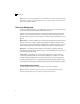
Workflow for Hardware Setup and Application Installation Control Surface R Grade InPr Curve OutPr GRADE CURVES Key KEY Geom G Hue B Bright 0019 #0001.00 Misc P&S Outside Inside GEOM P&S IN MISC OUT Bright Sh Mid High Brightness Saturation R+ G+ B+ + RGB- Shadow Contrast Brightnes s MORE F2 F1 F5 F4 F3 F6 MORE F8 F7 F9 Lustre Master Workstation 8 9 4 5 6 1 2 3 7 DO REDO UNDO CURSOR REVERT RECALL COMP OFFSET CLIP +/- GRADE 0 .
1 Introduction For workflow information related to the HP xw8400 running on Linux for Incinerator, refer to the Autodesk Incinerator 2009 Installation and User Guide. To install Lustre on an HP xw8400 workstation: 1. Review the guidelines for working with hardware components. See “Hardware Configuration Guidelines” on page 7. 2. Connect all peripherals (mouse, keyboard, graphics monitor, storage, etc.) to each workstation in your workgroup, and connect each workstation to the network.
Hardware Configuration Guidelines Installation and Configuration Guides Provides Hardware Setup Guide (for your workstation) Information on how to set up your workstation and video I/O peripherals. Stone Direct Configuration Guide Provides detailed connectivity diagrams and configuration procedures for your Stone storage arrays. Autodesk Lustre 2009 Software Installation Information about installing and licensing your Autodesk Lustre software.
1 Introduction Windows or Linux operating systems, HP xw8400 workstations, and peripherals associated with professional high-performance video and post production of film. Your Lustre system consists of high-performance hardware that must be configured in an environment suited to its operational needs. Other considerations include minimizing the risk of damage due to static discharge and ensuring all components are properly grounded.
Hardware Configuration Guidelines The Flash® System ROM confirmation menu appears. 9. Press F10 to confirm. 10. Press any key. System ROM Flash was successful appears. 11. Verify system BIOS settings. See “Verifying BIOS Settings” on page 10. 12. From the File menu, select Save Changes and Exit. To update the BIOS on a Linux workstation: 1. Load the DKU CD in the DVD-ROM drive on the workstation. 2. Open a terminal. 3.
1 Introduction System ROM Flash was successful appears. 14. Verify system BIOS settings. See “Verifying BIOS Settings” on page 10. 15. From the File menu, select Save Changes and Exit. Verifying BIOS Settings You do not normally need to adjust BIOS settings on your workstation. BIOS settings for the workstation are provided here for informational purposes only. To enter the system BIOS, press F10 while booting the workstation.
Hardware Configuration Guidelines 3. Press F10 to accept the changes. 4. Select Apply Defaults and Exit. This restores the original factory system defaults. Verifying and Updating the Graphics Card Driver A new graphic driver (NVIDIA® driver 165.46) is required for Lustre 2009 Windows systems. To upgrade the NVIDIA graphics card driver, complete the following instructions. To upgrade the NVIDIA graphics driver: 1.
1 Introduction Power and Air Conditioning Requirements The values for power consumption and heat output were recorded on an Autodesk certified system with all of the required peripheral and certified components. NOTE: These values can fluctuate if uncertified hardware components or third-party applications are added to your system. The use of uncertified hardware components or third-party applications is not supported.
Notation Conventions Grounding Hardware Components It is important to properly ground any audio components used with Lustre to avoid ground loops and humming. To ensure audio components are properly grounded, use the XLR-3 cables. Using any other cables may cause humming in the system. Receiving Your Lustre System When you receive the shipment containing your Lustre, check all the boxes for dents or other markings that may indicate damage during transport.
1 Introduction 14
Connecting Peripherals Summary Workflow for Connecting Peripherals . . . . . . . . . . . . . . . . . . . . . . . . . . . . . . . . . . . . . Connection Diagram for the HP xw8400 . . . . . . . . . . . . . . . . . . . . . . . . . . . . . . . . . . Connecting the Monitor . . . . . . . . . . . . . . . . . . . . . . . . . . . . . . . . . . . . . . . . . . . . . . . . . . Connecting the Keyboard, Mouse, and Monitor Calibration Device . . . . . . . . . Connecting Storage . . . . . . . . . . . . . . . . . . . . .
2 Connecting Peripherals Step: Refer to: 5. Connect the workstation to your network. “Network Connections” on page 19. 6. After you connect all the peripherals to your Lustre workstations, you can connect the workgroup components together. Chapter 3, “Connecting System Components,” on page 27. Connection Diagram for the HP xw8400 The following diagrams show the connections for the HP xw8400 workstation. NOTE: These diagrams provide an overview of video I/O connections.
Connecting the Monitor HP xw8400 Workstation (Linux - Incinerator only) HD-SDI (V2) Out 0:2:2/4:0:0 to 4:4:4 display device or VTR HD-SDI (V1) Out 4:2:2 to 4:2:2 or 4:4:4 display device or VTR To USB extender for mouse, keyboard, monitor calibrator To Incinerator GigE switch To DVS BOB To GFX monitor To InfiniBand switch Ref In from sync gen 0 to control surface, 1 to LAN, 3 to SAN Ref In from sync gen Connect to second DVI out on the main FX5500 card HD-SDI Out (B) to 4:4:4 VTR (dual link 0:2:2) HD-SDI
2 Connecting Peripherals Connecting the Keyboard, Mouse, and Monitor Calibration Device Connect the mouse, keyboard, and monitor calibration device to the workstation via the 4-port USB extender (TP.USB-EXT-400). To connect the keyboard and mouse: 1. Connect the USB keyboard to port 2 on the remote unit of the USB extender. 2. Connect the USB mouse to port 3 on the remote unit of the USB extender. 3. Connect the monitor calibration device (TP.
Network Connections You can connect your workstation to two types of storage: • One or more Stone Direct disk arrays that provide storage to individual workstations. Refer to the Stone Direct 2008 Configuration Guide for information on connecting disk arrays to your workstation. • A Storage Area Network (SAN) that provides shared storage for multiple workstations. Refer to the Autodesk Stone Shared Installation and Configuration Guide for information on connecting your workstation to a SAN.
2 Connecting Peripherals To install the Infiniband driver for use with a Windows-based Lustre workstation: 1. Download the driver package to a temporary location on your system. You can find the appropriate driver package here: ftp://ftp.discreet.com/pub1/release/lustre/lustre2008/drivers/SilverStormHCA.msi NOTE: Contact Customer Support if you have any problems downloading the driver package. See “Contacting Customer Support” on page 13. 2. Double-click the driver package and click Run.
Network Connections 5. On the Installation Options page, make sure no optional components are checked, then click Next. 6. On the Select Installation Folder page, browse for the correct path in which to install the driver. 7. Choose the system user permissions by selecting either the Everyone radio button or the Just me radio button. Click Next.
2 Connecting Peripherals 8. On the Confirm Installation page, click Next to begin the installation. The wizard displays an installation progress bar. 9. On the Installation Complete page, click Close. 10. On the Windows Desktop, right-click My Computer and select Properties in the drop-down menu. The System Properties dialog box appears. 11. Click the Hardware tab. 12. Click Device Manager. The Device Manager dialog box appears. 13. Right-click the PCI Device under Infiniband Host Channel Adapters.
Network Connections 18. In the Device Manager dialog box, right-click the first Infiniband port adapter. NOTE: There are two Infiniband port adapters. In the Device Manager, at this point, the adapters should each be indicated by the adapter icon with an exclamation mark through it. This shows that the adapter drivers are not yet installed. The Hardware Update Wizard appears. 19. Select No and click Next. 20. Select Install from a list or specific location and then click Next. 21.
2 Connecting Peripherals Repeat step 19 to step 22 for the second Infiniband port adapter. The Infiniband Host Channel Adapter and the two IP over IB port adapters should appear in the Device Manager dialog box, without exclamation marks on their icons. To optimize the Infiniband driver on Windows: NOTE: The Infiniband driver optimization steps are optional. 1. Go to the Network Connections panel. 2. Right-click on the connected IPoIB port and select Properties. 3. Click the Advanced tab. 4.
Network Connections 5.
2 Connecting Peripherals 4-Port Broadcom Adapter Connect the workstation to your facility’s network to access background rendering nodes, other Lustre Stations, and the facility’s NAS or SAN centralized storage (if applicable). You connect the ports on the Broadcom card as follows: • Connect Port 0 to the Autodesk control surface hub or the control surface itself. • Connect Port 1 to your house network. • Connect Port 2 to a SAN private network (optional).
Connecting System Components Summary Workflow for Connecting System Components in the Lustre Workgroup . . . . Connecting the Autodesk Control Surface . . . . . . . . . . . . . . . . . . . . . . . . . . . . . . . . . Assigning an IP Address to the Autodesk Control Surface . . . . . . . . . . . . . . . . . . . Configuring Lustre to Connect to the Autodesk Control Surface . . . . . . . . . . . . Connecting a Stand-Alone Tablet . . . . . . . . . . . . . . . . . . . . . . . . . . . . . . . . . . . . . . . . .
3 Connecting System Components Step: Refer to: 3. Connect a Slave Renderer to the Lustre workstation (Windows only). “Connecting the Slave Renderer to a Lustre Workstation” on page 33. 4. Connect the workstation to video I/O components. “Connecting Video I/O to a Master or HD Station” on page 36. 5. Connect the workstation to a high-speed “Connecting to a High-Speed Data Link Device (HSDL)” on page 39. data link device. 6. Connect the workstation to audio I/O components.
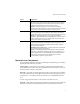
Connecting the Autodesk Control Surface To connect the Autodesk control surface: 1. Use the AC power adapter cables to connect each panel to a power supply. 2. Use a network cable to connect port 0 (the far right port) of the Broadcom network card on your workstation to port 1 on the Netgear ProSafe FS108 network switch.
3 Connecting System Components If you are using only one panel, you can connect that panel directly to the workstation, instead of using the switch. HP xw8400 Workstation To USB extender To port 1 on USB Extender Autodesk Activity Link System Power Autodesk Control Surface Tablet 5V DC 4A + Ethernet - 3. If you are using more than one panel, use network cables to connect each of the panels to the network switch. 4.
Assigning an IP Address to the Autodesk Control Surface NOTE: The above diagrams represent a Windows-based configuration. Components may differ slightly for the Linux configuration but the control surface connections are identical. Assigning an IP Address to the Autodesk Control Surface After you have connected the Autodesk control surface, you must assign it an IP address. To configure the Autodesk control surface on Windows-based workstations: 1. Click Start | Settings | Network Connections.
3 Connecting System Components 4. Select the Use the following IP address option. 5. Set a static IP and Subnet mask address for the port. Select values that do not conflict with any other machine on your network. Consider using the following values: • IP address: 192.168.125.10 • Subnet mask: 255.255.255.0 6. Click OK twice.
Configuring Lustre to Connect to the Autodesk Control Surface Configuring Lustre to Connect to the Autodesk Control Surface After you have configured the IP address of the control surface, you must configure Lustre to use the control surface. To configure Lustre to use the Autodesk control surface on Windows- or Linux-based workstations: 1. Turn the power on to each of the modules and look at the top display panel on the module. It should display the panel name and ID. 2.
3 Connecting System Components not available for the Linux-based version of Lustre, since it uses Incinerator to obtain real-time rendering and playback. Although the Slave Renderer uses a network connection, a higher Category 6 grade cable is needed to accommodate the data that is transmitted. For information on configuring the IP addresses of the network ports that connect the two workstations, see the Autodesk Lustre 2009 Software Installation Guide for Windows Workstations.
Connecting the Slave Renderer to a Lustre Workstation HP xw8400 Workstation (Windows-based) Slave Render Station (HP DL140 G3) Port 1 35
3 Connecting System Components Connecting Video I/O to a Master or HD Station You use the video components to set up video I/O and a broadcast monitor. The only video hardware you must provide are: a sync generator, a VTR, and an SD or HD SDI broadcast monitor. The following components are included in your hardware shipment. DVS Centaurus 1 or 2 board and DVS Breakout Box II — The DVS Centaurus board provides video I/O.
Connecting Video I/O to a Master or HD Station HP xw8400 Workstation Real-Time Deliverables* HD/SDI Display Device HD/SDI out (V1) 4:2:2 gfx feed HD/SDI out (V2) 0:0:2/4:0:0 gfx feed Used in 4:4:4 mode only From Altinex Comp Sync (HD) SDI In B from VTR (4:4:4)* (HD) SDI Out B to VTR (4:4:4)* To LTC on VTR or other slave device VTR Control RS-422 IN GPI AUDIO WClk CVBS RS 422A RS 422C RS.422B RS.
3 Connecting System Components Setting Up VTR Emulation You can configure your Autodesk Lustre 2009 application to emulate a VTR for output in real time. You control the emulator from the application or device that sees the Autodesk Lustre 2009 application as a VTR. The following procedure describes how to configure the hardware for VTR emulation. Consult the “VTR Emulation” chapter in the Autodesk Lustre 2009 User Guide for more information. To configure hardware for VTR emulation: 1.
Connecting to a High-Speed Data Link Device (HSDL) VTR Control Cable DVS REMOTE IN VTR SIDE 1 6 2 7 3 8 4 9 5 1 6 2 7 3 8 4 9 5 MALE DB9 MALE DB9 8 - TX 3 - TX + 2 - RX 7 - RX+ 4 - GND (SHIELD) WHT 2 - RX - BLK 7 - RX + RED 8 - TX - BLK 3 - TX+ GND 4 - GND (SHIELD) PAIR 1 PAIR2 Connecting to a High-Speed Data Link Device (HSDL) If you have purchased an HSDL license, you can connect to an HSDL device through the DVS Centaurus.
3 Connecting System Components Audio Wiring Workflow The following procedure provides the general workflow for setting up the audio subsystem for Lustre. To wire the audio subsystem: 1. Ensure that all of your workstation peripherals and video hardware components are properly connected. 2. Verify that you have all the required audio hardware components. See “Audio Hardware Components” on page 40. 3. Connect your audio hardware devices.
Connecting Audio Hardware IN GPI AUDIO WClk CVBS RS 422A RS 422C RS.422B RS.
3 Connecting System Components If you have a DVS video device with an ADAT converter, to connect the Lustre hardware components to the DVS breakout box, refer to the following diagram. DVS BOB (Front) IN OUT 1/2 3/4 5/6 7/8 1/2 3/4 5/6 7/8 RS.422A AUDIO WClk CVBS RS.
Connecting Audio Hardware Adjusting Lucid ADA 88192 Converter Settings You configure the converter through a series of setup menus that appear in the display on the front of the converter. Use the encoder dial and button immediately to the right of the display to navigate these menus and adjust settings. The top level setup menu contains the following menu items: ADAT, AES, Analog, Meter, Route, Sync, and System.
3 Connecting System Components Menu Menu Item Comment ADAT ADAT INs: SRC ON ADAT INs: SMUX OFF AES AES IN1+2: SRC OFF AES IN3+4: SRC OFF AES IN5+6: SRC OFF AES IN7+8: SRC OFF Analog Analog INs: SoftClip IN1+2: SoftClip ON IN3+4: SoftClip ON IN5+6: SoftClip ON IN7+8: SoftClip ON Analog Analog INs: Gain set each input channel to a value in the range -95.5 to +31.
index Index A D air conditioning requirements 12 audio hardware components 40 wiring workflow 40 Autodesk control surface assigning an IP address 31 configuration file 33 connecting 28 documentation set of guides 6 DVS I/O connecting 36 B BIOS settings HP xw8400 10 breakout box connecting 36 broadcast monitor connecting 36 C configuration guidelines grounding hardware 13 configuring Lucid ADA 88192 converter 42 connecting peripherals workflow 15 connecting system components workflow 27 connection diag
Index K T keyboard connecting 18 tablet connecting 33 L V Lucid ADA 88192 converter, configuring 42 Lucid Converter ADA 88192 40 monitor connecting 17 mouse connecting 18 video distributor amplifier connecting 36 video IO connections wiring for real-time deliverables 36 VTR connecting 36 emulation control cable 38 emulation, setting up 38 N W M network connection 19 P peripherals monitor 17 mouse and keyboard 18 network 19 tablet 33 power requirements 12 R real-time deliverables wiring 36 RS-