REVIT MODEL CONTENT STYLE GUIDE December 2009 Version 2.
Copyright© 2009 Autodesk, Inc. All Rights Reserved This publication, or parts thereof, may not be reproduced in any form, by any method, for any purpose. AUTODESK, INC., MAKES NO WARRANTY, EITHER EXPRESS OR IMPLIED, INCLUDING BUT NOT LIMITED TO ANY IMPLIED WARRANTIES OF MERCHANTABILITY OR FITNESS FOR A PARTICULAR PURPOSE REGARDING THESE MATERIALS, AND MAKES SUCH MATERIALS AVAILABLE SOLELY ON AN "AS-IS" BASIS. IN NO EVENT SHALL AUTODESK, INC.
Representation of the RAL Colors is done with the approval of RAL Deutsches Institut für Gütesicherung und Kennzeichnung e.V. (RAL German Institute for Quality Assurance and Certification, re. Assoc.), D-53757 Sankt Augustin. Typefaces from the Bitstream® typeface library copyright 1992. Typefaces from Payne Loving Trust© 1996. All rights reserved. AutoCAD 2006 is produced under a license of data derived from DIC Color Guide® from Dainippon Ink and Chemicals, Inc.
CONTENTS Feedback on the Guide 7 Audience 7 Definition: Quality Revit Content 7 Contents 8 Supplementary Files 8 Additional Files 9 Section 1: Planning Revit Model Content 10 Recommended Revit Release and Discipline for Content Creation 10 1.1 Determining Design Intent 11 Determining the Template to Use 11 Family Representations 12 1.2 Balancing Performance and Design Complexity 16 Design Intent vs.
Supported Content 26 Limitations 26 1.5 Planning a Revit Model Family 27 Section 2: Model Content Creation Standards 28 2.1 Workflow for Model Content Creation 29 Prototyping 30 2.2 Family Units 30 2.3 Family Naming Conventions 31 2.4 Type Naming Conventions 33 2.5 Category and Subcategory Standards and Usage 35 Adding Subcategories To Model Families 35 Subcategory Naming Conventions 36 2.
Option 2 – Apply Materials to Family Geometry by Category and Subcategory 55 Option 3 – Apply Materials with Custom Instance or Type Material Parameters 55 Example: Assigning Materials to a Table Family 56 2.12 Best Practices for Adding Connectors in Revit MEP Families 58 Adding a Connector 58 System Types 59 Connector Direction 60 Primary Connector 60 Linking Connector 61 Connector Mapping 62 Connector Descriptions 63 Section 3: Testing Guidelines 64 3.
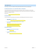
INTRODUCTION The purpose of this guide is to define Autodesk guidelines and standards for model content creation in Revit® Architecture, Revit® MEP, and Revit® Structure. Model content refers to the two‐dimensional and three‐ dimensional standard component families that are used to create elements that represent manufactured content (for example, windows, furnaces, heat pumps, and structural steel members).
• • • Parameter usage Performance – content designed to reduce the performance impact of the family on a project. Testing – thorough testing of the family parameters and types independently and in a project environment.
ADDITIONAL FILES The following resources are available for working with both Revit model content and Autodesk Seek. AUTODESK METADATA STYLE GUIDE AND PRODUCT WORKBOOK The Autodesk Metadata Style Guide defines styles and formatting rules that manufacturers, content service organizations, and content specialists must abide by so that the content that they produce can be loaded into the Autodesk Seek staging environment. Download at: http://seek.autodesk.com/participate.htm.
SECTION 1: PLANNING REVIT MODEL CONTENT In order to ensure Revit model content is developed efficiently and to Autodesk standards, content creators should follow Autodesk‐approved best practices when creating Revit families.
1.1 DETERMINING DESIGN INTENT When creating a Revit family, the intended use of the family in a project environment determines the extent to which it is designed. You can design all families to include a number of representations for use in different project views and project phases. The type and size of the project that a family is intended for use in is a critical point to consider when deciding what representations should be included in the family and what level of detail each representation should have.
FAMILY REPRESENTATIONS Depending on the intended use of a family, it may contain the following representations: • • • • Schematic (generic content; typically not manufacturer specific; may include multiple levels of detail) Design development (manufacturer‐specific content; typically Coarse level of detail) Construction document (manufacturer‐specific content; typically Medium level of detail) High quality rendering (manufacturer‐specific content; typically Fine level of detail) Depending on the use case
Schematic representations of a toilet family and of a table family DESIGN DEVELOPMENT Design development representations include more design detail than schematic representations, as well as 3D forms. They may also include basic materials.
Design development representation of a water softener: displays basic shapes of the softener and shows connectors CONSTRUCTION DRAWING Construction drawing representations are usually symbolic two‐dimensional representations.
Construction documentation representation of a water softener: displays a more realistic representation of the softener and its connections HIGH QUALITY RENDERING To define the appearance of family elements in high quality renderings, materials must be assigned to family geometry. Material properties and lighting must be defined.
1.2 BALANCING PERFORMANCE AND DESIGN COMPLEXITY The design complexity of a family can affect its performance when it is used to create elements in Revit projects. This is an important consideration when creating families that include a lot of geometry, multiple parametric relationships, and/or a large number of family types (sizes).
The following graph displays the general trend for the impact of design complexity on file size. Generally the more representations a family has and the more detailed they are, the larger the family file size. The larger the family file size is, the more of an impact it will have on performance (longer loading and regeneration times and greater increase in project file size).
RECOMMENDED FAMILY FILE SIZES To provide content creators with a tangible guideline for family file size, some common family types and their recommended file sizes are listed below. Use the file sizes below as a recommendation, as actual size may vary. Large, complex, and/or unusual families may exceed these recommendations.
LEVEL OF DETAIL Detail levels determine which pieces of family geometry display in different types of project views. When a Revit element is created with a family and added to a project view, the current detail level of the view (coarse, medium, or fine) displays the appropriate family geometry. INTENT: The intent is to build the family based on the expected fine representation, then remove detail to create the lower levels of detail.
ELEMENT VISIBILITY Typically, the geometry of an element created by a family will change depending on the current project view. The visibility settings of the family determine in which project views elements created with the family will display. In a plan view, you may want to see a 2D representation of the element. In a 3D or elevation view, you may want to display a fully detailed 3D representation of the element. In other views, you may want to hide the element.
EXAMPLES OF FAMILIES WITH APPROPRIATE AND COMPLEX LEVELS OF DETAIL The purpose of creating Revit families for manufactured content is not for the manufacturing process, but for architecture and engineering documentation deliverables. It is important to create the family content at an appropriate level of detail for the intended use. The following examples of a window family illustrate this guideline.
CONSIDERATIONS FOR NESTING FAMILY CONTENT A nested family is one that has been loaded into another family. In some cases, it can be convenient to represent parts of the nested family separately from the main family model. For example, you could create a windowsill family and nest it in a window family. This allows you to build upon previous work while creating families suited to your needs.
1.3 AUTODESK EXCHANGE FORMAT (.ADSK) Starting in the 2010 release of Autodesk products, the Autodesk Exchange format (.ADSK) provides an improved method for manufacturers to leverage Digital Prototypes to produce Revit Families. The Inventor 2010 AEC Exchange environment provides manufacturers with the ability to provide their existing Digital Prototypes as .
SIMPLIFYING THE GEOMETRIC REPRESENTATION As the typical Digital Prototype is modeled around manufacturing level of detail, it is suggested that a model simplification workflow be used to dramatically simplify and reduce the level of detail that is provided to AEC Customers. Without model simplification, the high level of detail that can be present in a Digital Prototype will have an adverse impact on model performance in the AEC application.
READING .ADSK FILES The .ADSK format can be read by Revit Architecture 2010, Revit MEP 2010, AutoCAD Architecture 2010, and AutoCAD MEP 2010 software versions or later. Information from the .ADSK file can be incorporated into the receiving application and saved out in the application’s native format. IMPORTING INTO REVIT FAMILIES ADSK files then can be imported into Revit Families for some post processing to help meet the requirements of the Revit Model Content Style Guide.
1.4 USING IMPORTED CONTENT Content created in other CAD formats may be imported and used to create Revit family content. Imported content may include geometry, metadata such as product performance information, connectors, and views. The use of such imported geometry does not offer all of the capabilities available with the .ADSK format (see Section 1.3) but is an option if .ADSK data is not available.
1.5 PLANNING A REVIT MODEL FAMILY Before family creation begins, careful upfront planning of the family should be performed, even for the simplest of families. Planning families prior to creation can save time and prevent errors. • Will the family need to accommodate multiple sizes? For a window that is available in several preset sizes, or a bookshelf that can be built in any length, create a standard component family.
SECTION 2: MODEL CONTENT CREATION STANDARDS In order to ensure Revit model content is developed efficiently, consistently, and to Autodesk standards, content creators should follow the Autodesk‐approved standards in this section when creating Revit families. Use the topics in this section to: • • • ensure consistency and stability of your Revit family content ensure a consistent user experience create content suitable to share on Autodesk Seek RMCSG — 28 Version 2.
2.1 WORKFLOW FOR MODEL CONTENT CREATION Before you create a model family, review the standards in this section, and then use the best practice workflow below to create your content. This workflow helps to ensure that your content is created in the most efficient and least error‐prone manner. 1. Create a new family file (.rfa) with the appropriate family template. 2. Define subcategories for the family to help control the visibility of the family geometry. 3.
PROTOTYPING If you need to create a number of similar families: 1. Plan and create a single “prototype” family. 2. Test the prototype family in the Family Editor and in a project environment to identify any errors or inconsistencies. See Section 3: Testing Guidelines for testing criteria. 3. Correct any errors and inconsistencies and retest the family to ensure it is works properly before creating the additional families. 2.
2.3 FAMILY NAMING CONVENTIONS Family names are the primary means of identifying families in Autodesk Seek and in the Revit software. Autodesk family naming conventions ensure that families can be identified in Autodesk Seek and the Revit software by the real‐world items that they create. The naming conventions include descriptors that allow the user to search for families by element, by manufacturer, and/or base units. GUIDELINES: • • • • • • • • • Create unique names for each family.
Examples Window–Double_Hung–Acme–Tilting_Sash–Clad.rfa Chiller–Air_Cooled– Acme– Low_Profile.rfa Fountain–Drinking–Acme–Polished_Chrome.rfa Window–Double_Hung–Generic–Wood.rfa Chiller‐Air_Cooled‐Acme‐Scroll‐(75‐100_Ton)‐Pkgd.rfa RMCSG — 32 Version 2.
2.4 TYPE NAMING CONVENTIONS All families must include one predefined type. For families that create real‐world objects that are available in standard sizes, predefined types should be generated. Unless they represent nominal sizes, type names should include units or capacity, and include a unit indicator. When naming a family type, use the format and rules below: GUIDELINES • • • • • • • Do not include the family name or category in the type name. Type names should mirror actual usage.
For unit‐specific families: For imperial family types: In most cases, size should be expressed in inches. Use only one of the conventions below within a family and for related families.
2.5 CATEGORY AND SUBCATEGORY STANDARDS AND USAGE All families, including generic families, must be assigned to appropriate categories and subcategories. When a family is created, it is assigned a category. The category defines its top level of identification (for example, Door, Window, or Casework) within the project environment. When the family is used in a project, the family can be located in the Project Browser under its category, and elements created by the family types will schedule by its category.
3. Determine if any of the additional subcategories fit your needs. 4. If the list does not contain the subcategories that you need, create new subcategories using the naming conventions in the next section. 5. Submit your subcategories to the Autodesk Seek team for approval. After they are approved, the subcategories will be added to the master list. SUBCATEGORY NAMING CONVENTIONS • • • • • RMCSG — 36 Create unique names for each subcategory. Use natural language to name the subcategory.
2.6 AUTODESK APPROVED PARAMETER USAGE Families contain parameters that not only create the family geometry, but identify or classify the elements that are created by the family. All families have predefined parameters that you assign values or data to, but you can add parameters that are not predefined in Revit software (that are not system parameters).
ADDING MANUFACTURER DATA TO FAMILIES Identity Data parameters in families can include manufacturer data, including information such as the model, description, assembly code, cost, and manufacturer URL. When elements are created with the family in a project, the parameters and associated values can be included in schedules.
CSI CLASSIFICATION CODES On Autodesk Seek, content families can be located by the appropriate CSI (Construction Specifications Institute) code. For best results, include information in 3 format standards: • MasterFormat 2004 – 50 divisions that standardize information in construction project manuals. • UniFormat II (Assembly Code) – Organizing preliminary construction information based on its systems and assemblies. Used for preliminary project descriptions, performance specifying and cost estimation.
ASSIGNING THE OMNICLASS CLASSIFICATION IN REVIT (REVIT 2010 AND LATER) The OmniClass 1.0 code is assigned to the family. You do not need to assign it to each family type. 5. In Revit, Open the Family Category and Parameters dialog. 6. Under Family Parameters, for OmniClass Number, click in the field, and click the browse button to select the appropriate OmniClass code from the dialog. Notice that the OmniClass Title value is added automatically. RMCSG — 40 Version 2.
2.7 PARAMETER NAMING CONVENTIONS Consistent parameter naming enables easier and more comprehensive parametric searching in Autodesk Seek. Create parameters only when variation creates meaningfully differentiated types that represent real‐world possibilities. GUIDELINES • Use standard approved parameter names when available. • Keep parameter names as short as possible. • Avoid abbreviation and truncation, when possible.
FORMAT required if the parameter applies to a sub‐component rather than the entire family. required for all parameters to describe the value being passed.
PARAMETERS THAT DESCRIBE THE LINEAR DIMENSION OF A SUB‐COMPONENT (CONNECTOR) Format: Connection • Hot Gas Bypass 2 Connection Diameter • Condenser Water Connection Diameter • Supply Air Connection Width • Supply Air Connection Height Version 2.
2.8 MATERIAL NAMING CONVENTIONS Finish material naming conventions organize the material by manufacturer, and general description to more specific description. Depending on the type of material, a finish material name may include a color, code, finish type, or identification number. GUIDELINES • • • Finish names should indicate the key differences between materials (manufacturer, type, color, finish) and, when applicable, reflect standard sizes.
FORMAT FOR INDIVIDUAL FINISH MATERIALS USING AN EXTERNAL IMAGE FILE Materials requiring external images, bump maps and cutout should be stored in a location that can be shared by multiple Revit Product installs. For Windows XP: C:\Documents and Settings\All Users\Application Data\Revit Manufacturer Library\Materials\ For Windows Vista and Windows 7: C:\ProgramData\All Users\Application Data\Revit Manufacturer Library\Materials\ GUIDELINES: • • • • • Create unique names for each unique material i
2.9 PREVIEW IMAGE STANDARDS A family preview image is a reduced thumbnail image of a 2D or 3D family view that graphically identifies a family before it is downloaded or opened.
CREATING AUTODESK STANDARD FAMILY PREVIEW IMAGES To create a preview image, begin by creating a family view to use exclusively for the preview image. Although you can save any family view as the preview image view, the best practice is to create a view that can be set to consistently display as is required for the preview image. After you create the view, set Autodesk standard graphic controls in the preview image view to ensure visual consistency with the preview images of other Revit families.
TO CREATE A DETAIL COMPONENT PREVIEW IMAGE: Create a view to use as the family preview image 1. If necessary, open the detail component family for which you want to create a preview image. Turn off visibility of dimensions and reference planes/lines 2. 3. 4. 5. Click View menu →Visibility/Graphics. In the Visibility/Graphic Overrides dialog, click the Annotation Categories tab. Under Visibility, clear Dimensions, Levels, Reference Lines, and Reference Planes. Click OK.
CREATING A HOSTED OR NON‐HOSTED MODEL COMPONENT PREVIEW IMAGE Depending on the type of model component that a preview image depicts, it may display a 2D or isometric view. If the preview image is created for a hosted family, host elements may or may not display in the preview. This topic presents general guidelines for creating preview images. For additional guidelines, refer to the category‐ specific documentation for model component preview images.
• Host‐based families other than doors and windows, such as light fixtures, may include host elements (walls or ceilings) in the preview image. Turn off visibility of dimensions and reference planes/lines in the view, as these elements may obscure component geometry if they display. TO CREATE A MODEL COMPONENT PREVIEW IMAGE: Create a view to use as the preview image 1. 2. 3. 4. 5. If necessary, open the family for which you want to create a preview image.
• For family previews in which the host should display, select all host categories. 11. Click OK. Set standard view controls in the Preview view 12. On the View Control Bar: • Click the current view scale, and depending on the family units, click 1 1/2” = 1’ ‐ 0” or 1:5. • Click Detail Level, and click Fine. • Click Model Graphics Style, and click Shading with Edges. Set the preview image to display the current view 13. Click File menu → Save As. 14.
2.10 TYPE CATALOG STANDARDS AND USAGE A type catalog is comma‐delimited TXT file that, when placed in the same directory as a family, displays a list of family types before the family is loaded into a project. You can select and load only the family types that the current project requires, avoiding an unnecessary increase in project size from unused types and a long list of types in the Type Selector.
Dialog displayed by the type catalog when the door family is loaded STRUCTURAL CONTENT – INDUSTRY‐STANDARD NAMING A type catalog (TXT file) for a steel joist family Dialog displayed by the type catalog when the steel joist family is loaded Version 2.
2.11 MATERIAL APPLICATION IN MODEL FAMILIES Materials can be applied to families to depict the real‐world display of elements created with the family in shaded and rendered views. IMPORTANT: When applying materials to a family, remember that materials increase the family size, which in turn decreases its performance when it is loaded and used in projects.
RESULT: When you create elements in a project with the family, you cannot: • • • change the element materials without editing the family change the material for instances or types of the family change the materials by assigning a material to the element category OPTION 2 – APPLY MATERIALS TO FAMILY GEOMETRY BY CATEGORY AND SUBCATEGORY You can apply materials to all or select pieces of family geometry by subcategory. Subcategories are categories that exist within the family category.
EXAMPLE: ASSIGNING MATERIALS TO A TABLE FAMILY In this example, a combination of material options is used to apply materials in a simple table family. Material assigned directly to geometry (Option 1): The hardware will not need to change when this family is used in a project, so a material is applied directly to the knob for the table drawer. In the Element Properties dialog for the knob geometry, under Materials and Finishes, the Material parameter value is set to Metal – Chrome.
The material for the table legs can be changed as required by the user in the project. In Element Properties, the Material property for the table legs geometry is associated with the Leg Material family parameter. The material for the legs therefore is determined by the material assigned to the Leg Material parameter in the Family Types dialog. The material for the table top can be changed by the user as required to match other furniture components in the project.
2.12 BEST PRACTICES FOR ADDING CONNECTORS IN REVIT MEP FAMILIES In Revit MEP, the connector connects the single family component with other components to create MEP systems. Without a connector, an RME family would just be a static placeholder. In Revit MEP, there are 3 kinds of connectors: • • • Electrical Connector Duct Connector Pipe Connector ADDING A CONNECTOR 1. 2. Click the tool for the connector you wish to add (Electrical Connector, Duct Connector, or Pipe Connector).
SYSTEM TYPES The following table provides an overview of the application scenario for each system type.
CONNECTOR DIRECTION For duct/pipe connectors, an arrow, perpendicular to the surface, displays. The direction that the arrow is pointing is also the direction in which the connecting duct/pipe will be drawn. As the picture shows, vertical duct can be drawn from an up connector in an air terminal. NOTE: The arrow does not represent the flow direction. PRIMARY CONNECTOR By default, the first connector in each domain is assigned as the primary connector.
For other families, the location of the primary connector is not important. LINKING CONNECTOR When there are more than one pipe/duct connectors, there is a choice for linking connectors. • • • Linked connectors only have an effect when the system type is set to global for equipment or fitting. Linking connectors on equipment makes it possible to propagate engineering data, allowing you to use equipment as an inline component in a system.
CONNECTOR MAPPING Edit Element Properties for the connector to define parameters for the connector. For part parameters, clicking a browse button displays a dialog that makes it easy to map connector parameters to family parameters with the same units. Connector mapping makes the connector parametric with the family. RMCSG — 62 Version 2.
CONNECTOR DESCRIPTIONS In the following example of complex equipment, it would be difficult to determine the function of each connector. To make it easier to identify the function of connectors in the family, add connector descriptions. These descriptions display in the Select Connector dialog. In the following image, descriptions are underlined in red for illustration purposes. Version 2.
SECTION 3: TESTING GUIDELINES To ensure the quality of Revit family content, thoroughly test families before using them in production or sharing them on Autodesk Seek.
3.1 GENERAL FAMILY TESTING GUIDELINES Perform general testing on a family when it is: • • open in the Family Editor loaded into a project Use the criteria in the checklists below to test families in each of the above environments. When testing families in projects, it is strongly recommended that you: • • • Test families in projects created with the generic metric and imperial testing template projects that were included in the download package.
PROJECT TESTING CRITERIA FOR REVIT ARCHITECTURE R Using a test project or one of the testing template projects available for download, load the family in a project environment, and check all views for anomalies. If the family includes a type catalog, use it to load the family. R Inspect the family appearance in all views (plan, reflected ceiling plan, elevation, Section, 3D) at all detail levels (Coarse, Medium, Fine).
3.2 FAMILY‐SPECIFIC TESTING GUIDELINES Depending on the type of family being tested, there may be specific criteria to test in addition to the general testing that should be performed on all families. Use this table to determine if a family requires any specific testing: REVIT FAMILY‐SPECIFIC TESTING Family Type Example Test Freely‐Placed Furniture, entourage Test in a relevant project context.