
2010


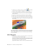
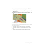


Table Of Contents
- Contents
- Part 1 Stress Analysis
- 1 Get Started With Stress Analysis
- 2 Analyze Models
- 3 View Results
- 4 Revise Models and Stress Analyses
- 5 Generate Reports
- 6 Manage Stress Analysis Files
- Part 2 Dynamic Simulation
- Index

2 In the ribbon bar, click the Dynamic Simulation tab to display the
simulation commands. Now we’ll add the sliding joint.
3 In the Joint panel, click Insert Joint. In the pull down list, select Sliding:
Cylinder Curve. For input 1 select the blade clamp slot profile on which
the follower rides.
4 For input 2, select the Follower cylinder face that rides in the slot. Click
OK.
5 Unlock the prismatic joint.
That completes this chapter on adding components and joints to the assembly.
In this chapter you learned to:
■ Add assembly components while in the simulation environment.
■ Add assembly constraints and see them automatically create standard
joints.
■ Add joints to simulate mechanical conditions within the assembly.
Add a Sliding Joint | 65