
2010
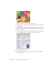

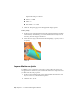


Table Of Contents
- Contents
- Part 1 Stress Analysis
- 1 Get Started With Stress Analysis
- 2 Analyze Models
- 3 View Results
- 4 Revise Models and Stress Analyses
- 5 Generate Reports
- 6 Manage Stress Analysis Files
- Part 2 Dynamic Simulation
- Index

3 Click the dof 1 tab. Click the joint forces command . Click Enable
joint force. Enter a Dry Friction coefficient of 0.1 and click OK.
4 We need to add a constraint to position the Scottish Yoke with respect
to the crank assembly. Set the browser view to Model and expand the
Blade set.iam node.
5 Expand the Scottish Yoke node and click the Constraint command.
6 In the browser, select Work Plane3 under the Scottish Yoke component.
7 In the graphics region, select a circular edge of the Roller component that
is part of the Crank cam assembly. A Point-Plane joint is added to reflect
the constraint.
The resulting Point-Plane joint has five degrees of freedom and one constraint.
This is enough definition to transfer motion without over constraining the
model. Dynamic Simulation detects over-constrained conditions and helps
you to resolve them.
Add a Sliding Joint
1 The next joint to add is the one between the blade set and the follower,
so that the follower travels in the blade clamp.
Before you create that joint, lock the Prismatic Joint between the Guide
and Follower components. This prevents the related components from
moving and lets the solver work more efficiently.
Right-click the Prismatic:3 (Guide:1, Follower:1) joint and click Lock dofs.
64 | Chapter 10 Construct Operating Conditions