
2010
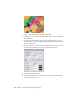

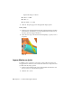


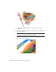

Table Of Contents
- Contents
- Part 1 Stress Analysis
- 1 Get Started With Stress Analysis
- 2 Analyze Models
- 3 View Results
- 4 Revise Models and Stress Analyses
- 5 Generate Reports
- 6 Manage Stress Analysis Files
- Part 2 Dynamic Simulation
- Index

7 Add a second mate constraint between the two components to position
the yoke within the guide rails. In the browser under Standard Joints, a
prismatic joint was created based on adding those constraints.
Add Friction
Add friction and complete the yoke-guide relationship
1 In the browser, right-click Blade set.iam and click Flexible. By setting the
assembly to Flexible, the assembly is placed into the welded group folder.
Within that assembly the constraints are evaluated and the constraint
between the yoke and blade causes the addition of a Revolution joint.
2 As was mentioned earlier, the assembly has no friction so far. This step
imposes friction on the prismatic joint. Right-click the Prismatic joint
for the Guide and Scottish Yoke, and click Properties.
Add Friction | 63