
2010
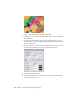


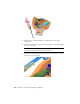

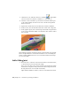
Table Of Contents
- Contents
- Part 1 Stress Analysis
- 1 Get Started With Stress Analysis
- 2 Analyze Models
- 3 View Results
- 4 Revise Models and Stress Analyses
- 5 Generate Reports
- 6 Manage Stress Analysis Files
- Part 2 Dynamic Simulation
- Index

3 Click Edit Joint Motion , and check Enable imposed motion.
4 Verify that Velocity is the selected Driving option.
5 In the input field, click the arrow to expand the input choices and click
Constant Value. Specify 10,000 deg/s
6 Click OK.
Run Simulations
Because the simulation is of a high speed device, modify the simulation
properties.
TIP Use the tooltips to see the names of the fields on the Simulation Player
Setting simulation options
1 On the Simulation Player, Final Time field, enter .5 s, which is sufficient
to demonstrate the mechanism.
NOTE The software automatically increases the value in the Images field
proportionally to the change in the Final Time field. Press the Tab key to
move the cursor out of the Final Time field to update the Images field.
2 In the images field, enter 200. Increasing the image count improves the
results you view in the Output Grapher.
3 Click Run on the Simulation Player.
As the Motor component drives the bevel gear, the remaining parts in
the kinematic chain respond.
The direction of gravity has nothing to do with any external notion of
"up" or "down," but is set according to the vector you specified.
Also, because we have not yet specified any frictional or damping forces,
the mechanism is lossless. There is no friction between components,
regardless of how long the simulation runs.
4 If the simulation is still running, click the Stop button on the Simulation
Player.
Run Simulations | 59