
2010
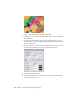

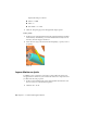


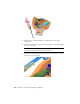

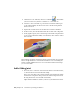
Table Of Contents
- Contents
- Part 1 Stress Analysis
- 1 Get Started With Stress Analysis
- 2 Analyze Models
- 3 View Results
- 4 Revise Models and Stress Analyses
- 5 Generate Reports
- 6 Manage Stress Analysis Files
- Part 2 Dynamic Simulation
- Index

6 Select circular sketch (2) on the roller component.
7 Click Apply. As you can see, sketch geometry can be used to help define
the simulation.
8 Drag the Follower until the roller contacts the cam. Notice it does not
penetrate. The 2D contact established a mechanical relationship between
the two components.
9 Set the properties for the 2D contact and display the force vector. In the
browser, right-click the 2D Contact joint and click Properties.
10 Set the Restitution values to 0.0.
11 Expand the dialog box to access the lower section. Check the Normal
box and set the Scale to 0.003.
56 | Chapter 9 Construct Moving Assemblies