
2010


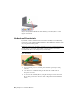

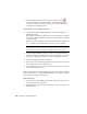


Table Of Contents
- Contents
- Part 1 Stress Analysis
- 1 Get Started With Stress Analysis
- 2 Analyze Models
- 3 View Results
- 4 Revise Models and Stress Analyses
- 5 Generate Reports
- 6 Manage Stress Analysis Files
- Part 2 Dynamic Simulation
- Index

3 Right-click the Srf1 node and click Visibility. The Bevel Gear construction
surface displays. We use this surface to help define the gear relationship.
4 At the right end of the ribbon panel, click Return. You are placed back
in the simulation environment.
5 On the ribbon, click Dynamic Simulation tab ➤ Joint panel ➤ Insert
Joint .
6 In the pull down list, select Rolling: Cone on Cone.
7 The Component selector command is active and waiting for input. Select
the Pitch Diameter circle at the base of the bevel gear conical surface (1).
8 Automatically, Component selector 2 is active and ready for input. Select
a conical face of a tooth on Bevel Gear 2. Do not select an involute face.
NOTE If necessary, expand the Mobile Groups and Cam crank browser nodes
to see the gear component.
The new joint is added to the browser below the Standard Joints node.
9 Click and drag Bevel Gear 1. You can see it move not only Bevel Gear 2,
but the entire Cam crank assembly.
Convert Assembly Constraints | 51