
2010
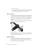

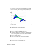
Table Of Contents
- Contents
- Part 1 Stress Analysis
- 1 Get Started With Stress Analysis
- 2 Analyze Models
- 3 View Results
- 4 Revise Models and Stress Analyses
- 5 Generate Reports
- 6 Manage Stress Analysis Files
- Part 2 Dynamic Simulation
- Index

2 Specify the contact type.
3 Select the appropriate entities for the contact type. If other components
are obscuring the component you want to select use Part selection option
to select the part first, then refine your selection thereafter.
Generate a Mesh
You can accept the default mesh settings and proceed right to the simulation.
At times there will be areas where you would like a mesh with greater density.
To manage this you can adjust the mesh settings or use a local mesh control.
If you want to view the mesh settings, click the Mesh Settings command in
the Prepare panel. You can specify the mesh settings you want for the
simulation.
After you define the meshes, click Mesh View to produce the mesh. The mesh
is generated as an overlay atop the model geometry.
Local Mesh Control
To apply a local mesh control, click the Local Mesh Control command in the
Prepare panel. Then, select the face where the mesh will be applied and specify
the mesh settings for the local control.
Run the Simulation
After you define the parameters for the analysis, you can run the simulation.
On the ribbon, click Stress Analysis tab ➤ Solve panel ➤ Simulate.
In the Simulate dialog box, you can expand the More section to see if there
are any process related notifications or warnings.
20 | Chapter 2 Analyze Models