
2010
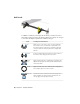
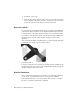

Table Of Contents
- Contents
- Part 1 Stress Analysis
- 1 Get Started With Stress Analysis
- 2 Analyze Models
- 3 View Results
- 4 Revise Models and Stress Analyses
- 5 Generate Reports
- 6 Manage Stress Analysis Files
- Part 2 Dynamic Simulation
- Index

Load-Specific InformationLoad
Specifies the direction of gravitational load on the model. Se-
lect a face to define the direction or use Vector Components
Gravity
to precisely control the direction. Cylindrical selections provide
an axial direction.
To add a load, you must:
1 Click the load command corresponding to the load type you want to
add.
2 The selection command is active so you can select the geometry
appropriate to the load you are defining.
3 Specify the load parameters. When needed, expand the dialog box to
access the advanced settings.
Double-click the load node in the browser to modify it. Alternatively, you can
right-click the load node and click Edit [type] constraint.
Add Contact Conditions
In assemblies, various contact conditions may exist. These are automatically
detected when using the Automatic Contacts command. The simulation
properties specify the tolerance and type of contact that will be automatically
assigned.
Review the contacts that are generated to ensure that these accurately represent
the physical interactions of your model. Only one contact type can serve as
the default for automatically inferred contacts, so some modification afterward
may be necessary.
Automatic Contacts
To automatically add contact conditions, click the Automatic Contacts
command. Alternatively, right-click the Contact node and click Automatic
Contacts.
Manual Contacts
At times it is necessary to manually add contacts. To manually add contact
conditions:
1 On the ribbon, click Stress Analysis tab ➤ Contacts panel ➤ Manual.
Add Contact Conditions | 19