
2010
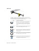
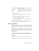
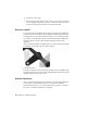

Table Of Contents
- Contents
- Part 1 Stress Analysis
- 1 Get Started With Stress Analysis
- 2 Analyze Models
- 3 View Results
- 4 Revise Models and Stress Analyses
- 5 Generate Reports
- 6 Manage Stress Analysis Files
- Part 2 Dynamic Simulation
- Index

Add Loads
To simulate conditions your design can encounter, you add force loads to
areas where such forces can be encountered. There are a variety of load types
to use. The following list explains the available load types.
Load-Specific InformationLoad
Apply a force to a set of faces, edges, or vertices. When the
force location is a face, the direction is automatically set to
Force
the normal of the face, with the force pointing to the inside
of the part. Define the direction planar faces, straight edges,
and axes.
Pressure is uniform and acts normal to the surface at all loca-
tions on the surface. Apply pressure only to faces.
Pressure
Apply a bearing load only to cylindrical faces. By default, the
applied load is along the axis of the cylinder and the direction
of the load is radial.
Bearing
Load
Apply a moment only to faces. Define direction using planar
faces, straight edges, two vertices, and axes.
Moment
Specifies the linear acceleration for the model using a face as
input. Cylindrical selections provide an axial direction. You
can only apply one body load per analysis.
Body Loads
18 | Chapter 2 Analyze Models