
2010
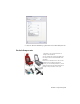
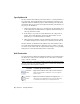
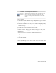
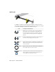
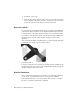

Table Of Contents
- Contents
- Part 1 Stress Analysis
- 1 Get Started With Stress Analysis
- 2 Analyze Models
- 3 View Results
- 4 Revise Models and Stress Analyses
- 5 Generate Reports
- 6 Manage Stress Analysis Files
- Part 2 Dynamic Simulation
- Index

Specify Material
The stress analysis environment provides the means to override materials for
any component. The default material provided in Inventor templates is not
completely defined for simulation purposes. When modeling your components,
use materials that are appropriate and completely defined, particularly if you
are going to use simulation.
1 Click Assign Materials. This step is optional based on the materials used
for the components. If all materials are completely defined materials, you
can forego material overrides.
2 In the dialog box, specify an override material for the components as
needed. The override material is listed in the third column. Use the
pulldown list to see what materials are available.
3 Make all necessary material overrides and failure criteria choices (Yield
or Ultimate Strength) used for Safety Factor calculations, then click OK.
Inventor materials are maintained through the Styles and Standards editor.
You can modify existing materials or define new ones according to your need.
You can access the editor from the Assign Materials dialog box or by clicking
Manage tab ➤ Styles and Standards panel ➤ Styles Editor.
Add Constraints
You add constraints to mimic environmental conditions. Constraint instances
are child nodes of the browser Constraints node. Double-click a constraint
node to edit the constraint.
NOTE Constraints are a crucial part of building a simulation model and can greatly
affect the end results of the simulation. Take time to consider them carefully and
accurately represent the physical conditions,
Constraint-Specific InformationConstraint
Apply a fixed constraint to a face, edge, or vertex in the part.
Apply a fixed constraint to establish zero or non-zero displace-
ment on a part.
Fixed Con-
straint
Apply a pin constraint on cylindrical faces. Apply pin con-
straints to prevent cylindrical faces from moving or deforming
in combinations of radial, axial, or tangential directions.
Pin Con-
straint
16 | Chapter 2 Analyze Models