
2009


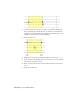
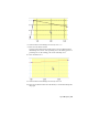


Table Of Contents
- Contents
- Stress Analysis
- 1 Get Started With Stress Analysis
- 2 Analyze Models
- 3 View Results
- 4 Revise Models and Stress Analyses
- 5 Generate Reports
- 6 Manage Stress Analysis Files
- Simulation
- Index

Add torque to the joint between the pillar and link parts.
9 Right-click Revolution (pillar:1, link:1), and then select Properties.
10 Click the DOF 1 (R) tab.
11 Click the Edit Joint Torque button.
12 On the Edit Joint Torque dialog box, select the Enable joint torque check
box.
13 In the Damping field, enter 50 N mm s/deg.
14 Click OK.
Output grapher
1 Click the Output Grapher tool.
2 In the Output Grapher browser, expand Standard Joints, and expand
Revolution:2 (pillar:1, link:1).
3 Expand the Revolution Force folder, and then select Force.
4 Run the simulation. As the simulation runs, the Output Grapher plots a
visual representation of the force.
NOTE The graph scale adjusts automatically to fit the curve.
Prepare for FEA
1 On the Dynamic Simulation panel bar, click Dynamic Simulation Settings.
2 On the Dynamic Simulation Settings dialog box, click AIP Stress Analysis.
3 Click OK.
Select parts
1 On the Output Grapher toolbar, click Export to FEA.
2 On the Export to FEA dialog box, click the selection arrow to activate
part selection, if necessary.
3 In the graphics window, click link:1.
Output Grapher | 77