
2009
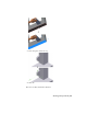
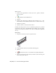
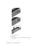


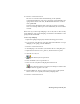


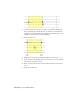
Table Of Contents
- Contents
- Stress Analysis
- 1 Get Started With Stress Analysis
- 2 Analyze Models
- 3 View Results
- 4 Revise Models and Stress Analyses
- 5 Generate Reports
- 6 Manage Stress Analysis Files
- Simulation
- Index

Simulation Tools
This chapter tells you how to vary the joint torque using the Input Grapher, how to analyze
a simulation using the Output Grapher, and how to export a load to Stress Analysis in
Autodesk
®
Inventor
™
Simulation.
Input Grapher
Like the force, the damping value is also constant. You can change the damping
value to a variable.
1 Right-click Revolution:1 (door:1, pillar:1), and then select Properties.
2 Click the DOF 1 (R) tab.
3 Click the Edit Joint Torque button.
4 Click the Input Grapher button located next to
Damping field.
Input Grapher is used to vary the joint torque. The vertical axis of the graph
represents torque load. The horizontal axis represents time. The torque
plot is represented by the red line.
Vary the joint torque
1 Double-click the line near the 0.25 time value to add a new datum point.
10
73