
2009
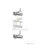


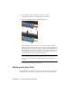

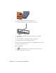
Table Of Contents
- Contents
- Stress Analysis
- 1 Get Started With Stress Analysis
- 2 Analyze Models
- 3 View Results
- 4 Revise Models and Stress Analyses
- 5 Generate Reports
- 6 Manage Stress Analysis Files
- Simulation
- Index

that its X, Y, Z-axes are derived from the selected geometry and have nothing
to do with the part or assembly coordinate systems.
Another difference is that the joint triad uses shapes rather than color to
differentiate the axes. The X vector is indicated with a single arrow head. The
Y vector uses a double arrow. The Z vector uses a triple arrow.
NOTE It is not necessary to specify the X-axis, unless a specific X-axis is needed
for a particular action in the Output Grapher.
Create a joint
1 Drag the jack stem away from the bracket far enough that the hole on
the bracket is visible.
2 Click the Insert Joint tool.
3 On the Insert Joint dialog box, select Cylindrical on the Joint menu.
4 Keeping the hole in the jack stem clevis and the hole in the bracket
parallel, select the hole on the jack stem clevis.
5 Right-click, and then select Continue.
6 Select the hole on the bracket.
Working with Joint Triad | 63