
2009
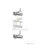


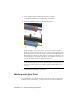

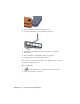
Table Of Contents
- Contents
- Stress Analysis
- 1 Get Started With Stress Analysis
- 2 Analyze Models
- 3 View Results
- 4 Revise Models and Stress Analyses
- 5 Generate Reports
- 6 Manage Stress Analysis Files
- Simulation
- Index

2 In the graphics window, right-click and select Continue.
It enables the selection tools in the Component 2 field.
3 Select the cylindrical surface of the jack stem part (3).
In this example, it is not necessary to specify the origins and X-axes.
However, it is necessary that the Z-axes on the two parts align and point
in the same direction. For most joint types, the Z-axes of the two selections
must align and point in the same direction. For these two selections, the
Z-axes happen to point in the same direction by default. As needed, you
can use the Switch Z button to flip the Z direction.
NOTE The selection order is important, so first select the cylindrical surface
of the jack body, and then select the cylindrical surface of the jack stem. To
undo any selection, click a selection button again, and then make a new
selection.
4 On the Insert Joint dialog box, click OK.
Working with Joint Triad
In a general sense, the joint triad is like the 3D Move/Rotate tool and the 3D
Indicator in that it indicates X, Y, Z-axes. However, the joint triad differs in
62 | Chapter 9 Construct Moving Assemblies