
2009
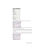
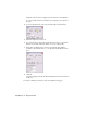
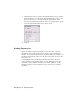
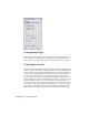
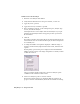
Table Of Contents
- Contents
- Stress Analysis
- 1 Get Started With Stress Analysis
- 2 Analyze Models
- 3 View Results
- 4 Revise Models and Stress Analyses
- 5 Generate Reports
- 6 Manage Stress Analysis Files
- Simulation
- Index

Setting Analysis Type
Before starting your solution, on the Settings dialog box, Analysis Type, select
Stress Analysis, Modal Analysis (to perform resonant frequency analysis) or
Both (to run a stress analysis and a prestressed modal analysis of your part).
Setting Mesh Control
There are two meshing model types: standard solid model and optimized thin
model. For a part, the default is standard solid model. It can be meshed in all
X, Y, and Z directions. The default meshing model for sheet metal is optimized
thin model. It is assumed that the model is thin in one direction relative to
the size of the other dimensions, has identical topologies on the top and
bottom, and has only one topology through the thickness of the model. On
the Settings dialog box, move the Mesh Relevance slider to set the size of your
mesh. The default value of zero is an average mesh. Setting the slider to 100
causes a fine mesh to be used. It gives you a highly accurate result, but causes
the solution to take a longer time. Setting the slider to -100 gives you a coarse
mesh, which solves quickly, but may contain significant inaccuracies. The
Mesh Relevance and Result Convergence only work for the standard solid
22 | Chapter 2 Analyze Models