
2009
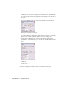
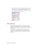
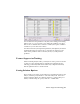
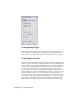
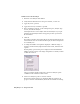
Table Of Contents
- Contents
- Stress Analysis
- 1 Get Started With Stress Analysis
- 2 Analyze Models
- 3 View Results
- 4 Revise Models and Stress Analyses
- 5 Generate Reports
- 6 Manage Stress Analysis Files
- Simulation
- Index

3 Click the More button to specify a fixed displacement for the constraint,
if needed. Check Use Components, and then check the box next to the
global axis label (X, Y, or Z) along which the displacement occurs.
You can use parameters and negative values. Use Components to specify
a non-zero displacement that can be used as a load.
4 Click OK.
Setting Parameters
When you define loads and constraints for a part, the values you enter
(magnitudes, vector components, and so on) are stored as parameters in
Inventor. It automatically generates the parameter names. For example, load
parameters are labeled dn, where d0 is the first load created, d1 the second
load, and so on.
Load magnitude and constraint displacement values can be entered as
equations when you are defining them. Or, after defining the loads and
constraints, select Parameters from the stress analysis panel bar. On the
Parameters dialog box, enter equations for any of the load or constraint
parameters.
20 | Chapter 2 Analyze Models