
2009
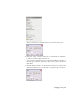
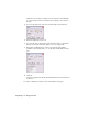
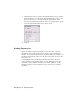
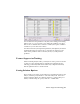
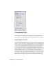
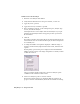
Table Of Contents
- Contents
- Stress Analysis
- 1 Get Started With Stress Analysis
- 2 Analyze Models
- 3 View Results
- 4 Revise Models and Stress Analyses
- 5 Generate Reports
- 6 Manage Stress Analysis Files
- Simulation
- Index

This table summarizes information about each load type:
Load-Specific InformationLoad
Apply a force to a set of faces, edges, or vertices. When the
force location is a face, the direction is automatically set to
Force
the normal of the face, with the force pointing to the inside
of the part. Define the direction planar faces, straight edges,
and axes.
Pressure is uniform and acts normal to the surface at all loca-
tions on the surface. Apply pressure only to faces.
Pressure
Apply a bearing load only to cylindrical faces. By default, the
applied load is along the axis of the cylinder and the direction
of the load is radial.
Bearing
Load
Apply a moment only to faces. Define direction planar faces,
straight edges, two vertices, and axes.
Moment
Select a direction from the Earth Standard Gravity list to apply
gravity. Select the Enable check box under Acceleration or
Body Loads
Rotational Velocity. You can only apply one body load per
analysis.
Applying Constraints
After you define your loads, specify the constraints on the geometry of the
part. You can apply as many constraints as you need. The defined constraints
are listed in the browser under Loads & Constraints. After you define a
constraint, you can edit it by right-clicking it, and then selecting Edit from
the menu.
Select and apply a constraint
1 On the Stress Analysis panel bar, click Fixed Constraint, Pin Constraint,
or Frictionless Constraint.
2 In the graphics window, select a set of faces, edges, or vertices to constrain.
The location arrow turns white.
Applying Constraints | 19