
2009
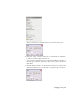
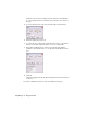
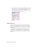
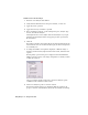
Table Of Contents
- Contents
- Stress Analysis
- 1 Get Started With Stress Analysis
- 2 Analyze Models
- 3 View Results
- 4 Revise Models and Stress Analyses
- 5 Generate Reports
- 6 Manage Stress Analysis Files
- Simulation
- Index

Workflow: Perform a typical analysis
1 Enter the stress analysis environment.
2 Verify that the material used for the part is suitable, or select one.
3 On the Stress Analysis panel bar, select the type of load to apply. The
choices are Force, Pressure, Bearing Load, Moment, Body Load, Motion
load (for a part exported from Dynamic Simulation), or Fixed Constraint.
4 On the model, select the faces, edges, or vertices where you want to apply
the load.
5 Enter the load parameters (for example, on the Force dialog box, enter
the magnitude and direction). Numerical parameters can be entered as
numbers or equations that contain user-defined parameters.
6 Repeat steps 3 through 5 for each load on the part.
7 Apply constraints to the model.
8 Change stress analysis environment settings as needed.
9 Modify or add parameters as needed.
10 Start the analysis.
11 View the results.
12 Change the model and reanalyze it until you simulate the appropriate
behavior.
Verifying Material
The first step is to verify that your model material is appropriate for stress
analysis. When you select Stress Analysis, Autodesk
®
Inventor
™
checks the
material defined for your part. If the material is suitable, it is listed in the
Stress Analysis browser. If it is not suitable, a dialog box is displayed so that
you can select a new material.
Verifying Material | 15