
2010

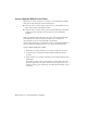


Table Of Contents
- Contents
- Part 1 Tubes and Pipes
- 1 Get Started with Tube & Pipe
- 2 Route Basics
- 3 Set Styles
- 4 Create Rigid Routes and Runs
- Workflow for Rigid Routes
- Create Auto Route Regions
- Manually Create Parametric Regions
- Automatically Dimension Route Sketches
- Create Segments With Precise Values
- Define Parallel and Perpendicular Segments
- Snap Route Points to Existing Geometry
- Place Constraints On Route Sketches
- Create Bends Between Existing Pipe Segments
- Create Pipe Routes With Custom Bends
- Create Bent Tube Routes
- Realign 3D Orthogonal Route Tool
- Control Dimension Visibility
- Populated Routes
- 5 Create and Edit Flexible Hose Routes
- 6 Edit Rigid Routes and Runs
- 7 Use Content Center Libraries
- 8 Author and Publish
- 9 Document Routes and Runs
- Part 2 Cable and Harness
- 10 Get Started with Cable and Harness
- 11 Work With Harness Assemblies
- 12 Use the Cable and Harness Library
- 13 Work with Wires and Cables
- 14 Work with Segments
- 15 Route Wires and Cables
- 16 Work with Splices
- 17 Work with Ribbon Cables
- 18 Generate Reports
- 19 Work With Nailboards and Drawings
- Part 3 IDF Translator
- Index

Snap Route Points to Existing Geometry
The Point Snap tool helps you to create route points by snapping to faces,
edges, work points, or vertices.
In this exercise, you continue defining the route point by snapping to the
path part.
Snap route points to existing geometry
1 On the ribbon, click Route tab ➤ Create panel ➤ Route.
2 Click the left circular opening on the valve part.
3 Right-click in the graphics window and select Point Snap.
4 Move the cursor over the last segment you just created in the preceding
exercise.
A dashed line representing the snap point is displayed from the cursor
to the preview point. A preview point is displayed at the intersection of
the line and the axis.
Snap Route Points to Existing Geometry | 65