
2010
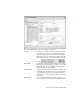

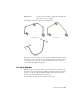


Table Of Contents
- Contents
- Part 1 Tubes and Pipes
- 1 Get Started with Tube & Pipe
- 2 Route Basics
- 3 Set Styles
- 4 Create Rigid Routes and Runs
- Workflow for Rigid Routes
- Create Auto Route Regions
- Manually Create Parametric Regions
- Automatically Dimension Route Sketches
- Create Segments With Precise Values
- Define Parallel and Perpendicular Segments
- Snap Route Points to Existing Geometry
- Place Constraints On Route Sketches
- Create Bends Between Existing Pipe Segments
- Create Pipe Routes With Custom Bends
- Create Bent Tube Routes
- Realign 3D Orthogonal Route Tool
- Control Dimension Visibility
- Populated Routes
- 5 Create and Edit Flexible Hose Routes
- 6 Edit Rigid Routes and Runs
- 7 Use Content Center Libraries
- 8 Author and Publish
- 9 Document Routes and Runs
- Part 2 Cable and Harness
- 10 Get Started with Cable and Harness
- 11 Work With Harness Assemblies
- 12 Use the Cable and Harness Library
- 13 Work with Wires and Cables
- 14 Work with Segments
- 15 Route Wires and Cables
- 16 Work with Splices
- 17 Work with Ribbon Cables
- 18 Generate Reports
- 19 Work With Nailboards and Drawings
- Part 3 IDF Translator
- Index

menu from the appropriate rows in the components
table. Suppressed fittings are not included in the flex-
ible hose route. If you suppress the start fitting, the
end fitting is automatically suppressed.
Determines the structure of the hose as either a flat
structure or a subassembly.
Use subassembly
For more information about parameters, see
Set Style Options on page 41 in
this chapter.
NOTE You cannot apply a rigid type style to an existing flexible hose route and
vice versa. To change between a rigid style and flexible hose style, you must delete
the route and create a new one using the flexible hose style.
Structure Flexible Hose Routes
When defining the flexible hose style you must decide if you want the fittings
placed into either a flat structure or a subassembly.
All parts are independent components placed along
with all other components under the pipe run. There
is no subassembly.
Flat structure
All parts are grouped into a subassembly under the
pipe run.
Subassembly struc-
ture
The route structure used for your design is typically determined by how the
hose route parts are purchased, assembled, and represented in manufacturing
documentation such as Parts Lists and Bills of Materials (BOM).
Create Flexible Hose Styles
In the following exercises, you create several hose styles based on the
predefined Hydraulic Hose - Female Thread - Swivel style.
Create a Flexible Hose style with both fittings
1 In the style browser, select Hydraulic Hose - Female Thread - Swivel.
2 Copy and edit the style as you did previously.
3 Enter the new style name, Hydraulic Hose- Female Thread - Swivel (1/2 ND
2) to indicate the nominal size and two hose fittings, and click Save.
48 | Chapter 3 Set Styles