
2010
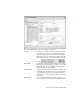


Table Of Contents
- Contents
- Part 1 Tubes and Pipes
- 1 Get Started with Tube & Pipe
- 2 Route Basics
- 3 Set Styles
- 4 Create Rigid Routes and Runs
- Workflow for Rigid Routes
- Create Auto Route Regions
- Manually Create Parametric Regions
- Automatically Dimension Route Sketches
- Create Segments With Precise Values
- Define Parallel and Perpendicular Segments
- Snap Route Points to Existing Geometry
- Place Constraints On Route Sketches
- Create Bends Between Existing Pipe Segments
- Create Pipe Routes With Custom Bends
- Create Bent Tube Routes
- Realign 3D Orthogonal Route Tool
- Control Dimension Visibility
- Populated Routes
- 5 Create and Edit Flexible Hose Routes
- 6 Edit Rigid Routes and Runs
- 7 Use Content Center Libraries
- 8 Author and Publish
- 9 Document Routes and Runs
- Part 2 Cable and Harness
- 10 Get Started with Cable and Harness
- 11 Work With Harness Assemblies
- 12 Use the Cable and Harness Library
- 13 Work with Wires and Cables
- 14 Work with Segments
- 15 Route Wires and Cables
- 16 Work with Splices
- 17 Work with Ribbon Cables
- 18 Generate Reports
- 19 Work With Nailboards and Drawings
- Part 3 IDF Translator
- Index

NOTE Before you make changes to a system style, make a copy and give it a new
name. You can then select the system style from the browser and make the
modifications.
To create a new style from a blank one, select the style type to create, and
then click New. This leaves the basic requirements for the style type as a guide,
but clears all values.
Create Rigid Pipe with Fittings Styles
When creating rigid pipe styles, the required components depend on the type
of rigid style being created.
■ Typically three compatible parts are required: a pipe, a coupling, and an
elbow. If you require both 45-degree and 90-degree elbows, four parts are
required.
■ Self Draining styles require five components: a pipe, a coupling, a 45-degree
elbow, a 90-degree elbow, and a previously published custom elbow or tee
that matches the slope angle.
■ Welded tube and pipe styles typically need two part types: a pipe and a
90-degree elbow. Butt welded styles require you to set a gap size for the
groove welds and determine whether to display the gaps in the graphics
window and drawings.
■ Flanged styles require: a pipe, an elbow, a flange instead of a coupling, and
an optional gasket.
In this exercise, you create two new rigid piping styles using existing styles as
the base.
NOTE When you switch between styles or create new styles during edits, you are
prompted whether or not to save edits. Click Yes to save edits to the current style
before proceeding or click No to proceed without saving changes to the current
style.
Create rigid piping styles
1 With the AirSystemAssy.iam assembly open, activate the master runs
assembly Tube & Pipe Runs or the AirSystem1:1 run.
Create Rigid Pipe with Fittings Styles | 45