
2010
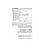

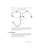


Table Of Contents
- Contents
- Part 1 Tubes and Pipes
- 1 Get Started with Tube & Pipe
- 2 Route Basics
- 3 Set Styles
- 4 Create Rigid Routes and Runs
- Workflow for Rigid Routes
- Create Auto Route Regions
- Manually Create Parametric Regions
- Automatically Dimension Route Sketches
- Create Segments With Precise Values
- Define Parallel and Perpendicular Segments
- Snap Route Points to Existing Geometry
- Place Constraints On Route Sketches
- Create Bends Between Existing Pipe Segments
- Create Pipe Routes With Custom Bends
- Create Bent Tube Routes
- Realign 3D Orthogonal Route Tool
- Control Dimension Visibility
- Populated Routes
- 5 Create and Edit Flexible Hose Routes
- 6 Edit Rigid Routes and Runs
- 7 Use Content Center Libraries
- 8 Author and Publish
- 9 Document Routes and Runs
- Part 2 Cable and Harness
- 10 Get Started with Cable and Harness
- 11 Work With Harness Assemblies
- 12 Use the Cable and Harness Library
- 13 Work with Wires and Cables
- 14 Work with Segments
- 15 Route Wires and Cables
- 16 Work with Splices
- 17 Work with Ribbon Cables
- 18 Generate Reports
- 19 Work With Nailboards and Drawings
- Part 3 IDF Translator
- Index

You can also set additional filtering, such as material and industry standard
to further refine the list. The standards and materials of published parts are
listed. Use the lists to make your selections. Once the standard is selected, the
available materials for the standard are listed. When an asterisk is displayed,
the system returns all content for that setting. For example, the system allows
all (*/any) materials to appear in the results.
Rules Tab
The Rules tab sets parameters that specify the size range for creating route
segments between identified route points. It includes the minimum and
maximum values, as well as the increment round-off value. Other settings are
specific to the type of style being created:
■ For bent tube routes, you can set the default bend radius for the bends.
Rules Tab | 43